European
Nuclear Society
e-news
Issue 19 Winter 2008
http://www.euronuclear.org/e-news/e-news-19/icapp.htm
2006 International Congress on Advances in Nuclear Power Plants
Embedded International Topical Meeting at the 2006 ANS Annual Meeting
ICAPP '06 • June 4-8, 2006 • Reno, NV • Reno Hilton
University of FloridaDryout of BWR Fuel Elements
Frigyes Reisch Nuclear Power Safety, KTH Royal Institute of Technology, Stockholm, Sweden
Phone/fax +46 8 7202365
Frigyes@safety.sci.kth.se
1. INTRODUCTION
The surface temperature of the fuel limits the power production of nuclear
reactors. Intense high temperatures can damage the fuel cladding and cause
a radioactive release and even provoke in-vessel accident resulting in particulate
debris bed, or core melt down. Therefore, identifying the uppermost permitted
surface temperature in a Light Water Reactor (LWR) is of great importance.
The experiments described here define the maximum permissible power production
of Boiling Water Reactors (BWR) fuel element without the risk of burnout. As
witnessed by a great number of publications, the search is going on for reliable
criteria to assure the safety of the fuel. Here one such criteria is analysed.
Normally the fuel surface is effectively cooled by boiling water. However,
when the heat flux exceeds a critical value the heat transfer from the fuel
surface into the coolant deteriorates, with the result that a drastically increased
fuel surface temperature occurs. Excessive fuel temperature can be caused by
overpower or reduced coolant flow. At neutronics and thermal-hydraulic power
oscillations when the duration of the power peaks are very short, temporary
high temperature can occur without causing fuel failures as normal cooling
can quickly recover. To avoid excessive fuel temperature, the knowledge of
the onset of the overheating phenomena is absolutely necessary, both at the
design stage and during the safe operation of a reactor. There are complex
correlations especially developed for specific fuel bundle designs. These correlations
contains surface power, mass flow, system pressure and other parameters. While
analyzing the test results it was recognised that a single parameter, the void,
characterises the onset of the overheating phenomena in a wide range of pressure
and flow conditions. These results were attained from the experimental loop
especially developed to study the dryout of BWR fuel elements.
2. MECHANISMS OF CRITICAL HEAT FLUX
Normally the fuel surface is effectively cooled by boiling water. However,
if the heat flux exceeds a critical value the heat transfer from the fuel surface
into the coolant that deteriorats, with the result a drastically increased
fuel surface temperature occurs. The mechanisms of critical heat flux are:
a) Formation of hot spots under a growing bubble. Here when a bubble grows
at the heated wall a dry patch forms underneath the bubble as the micro-layer
of liquid under the bubble evaporates. In this dry zone, the wall temperature
rises due to the deterioration in heat transfer.
b) Near-wall bubble crowding and inhibition of vapor release. Here a “bubble
boundary layer” builds up on the surface and vapor generated by boiling
on the surface must escape through this boundary layer. When the boundary layer
becomes too crowded with bubbles, vapor escape is impossible and liquid cannot
penetrate to the heated wall and cool it, the surface becomes dry and overheat
gives rise to burnout.
c) Dryout under a slug or vapor clot. In plug or slug flow, the thin film surrounding
the large bubble may dry out giving rise to localized overheating and hence
burnout. Alternatively, a stationary vapor slug may be formed on the wall with
a thin film of liquid separating it from the wall, in this case, localized
drying out of this film gives rise to overheating and burn out.
d) Film dryout in annular flow
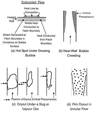
Figure 1. Critical Heat Flux Mechanisms
3. EXCESSIVE FUEL TEMPERATURE
Excessive fuel temperature can be caused by overpower or by reduced coolant
flow. At thermal power and/or hydraulic oscillations when the power peaks and/or
the flow reductions are very short and few, temporary over temperature (above
the designed limit) can occur without causing fuel failures as normal cooling
can quickly recover. To avoid excessive fuel temperature, which can cause damage
to the fuel, knowledge of the onset of the over heating phenomena is absolutely
necessary, both at the design stage and during the safe operation of a reactor.
There are complex correlations especially developed for specific fuel bundle
designs. These correlations contain surface power, mass flow, system pressure
and other parameters. While analyzing the test results for a single fuel pin
in water and steam in an annular test section, it was recognized that a single
parameter, the void, is characterizing the onset of the overheating phenomena
regardless which critical heat flux mechanism occurred.
4. MEASUREMENTS
Measurements were been carried out in a two-phase flow test loop consisting
of two heated concentric tubes, the central one representing a fuel rod while
the outer pipe emanates the heating power corresponding to the surrounding
fuel rods in a reactor core. This loop with an anular test section height of
7 m is presently located at the Division of Nuclear Engineering, KTH, Royal
Institute of Technology, in Stockholm and has been in operation for some thirty
years first at the Studsvik research establishment and then at KTH to simulate
thermal hydraulic conditions in Boiling Water Reactors. (Figure 2)
Total Power: 1 MW
Total mass flow rate: 1 kg/s
Max pressure: 25 Mpa.
Max lengt of the test section: 7m.
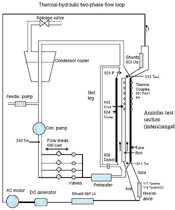
Figure 2. The loop and the test section
5. TEST RESULTS
The results of these tests were studied to investigate the occurrence
of the onset of the excessive temperature on the surface of the inner and outer
test tubes in this annular flow system. The tests covered pressures of 30,
50 and 70 bar; sub-cooling 10ºC and 40ºC; mass velocities between
250 and 2250 kg/m2s and a total input power up to 580 kW, in this
case with uniform power distribution. The tests have been repeatedly performed
in an annular test section with a single fuel rod furnished with pin spacers,
and 7 and 6 grid spacers alternatively. Then the test results were evaluated.
To calculate the steam quality, the continuity, the heat and mass balance equations
were applied.
Heat balance
Qtotal input = Qsubcooling to saturation + Qsteam building (1)
Q heat
Qsubcooling to saturation heat used to increase the temperature of the subcooled water to saturation temperature
Qsteam building heat used for vaporization of part of the saturated water to steam
Mass balance
Winlet water = Wexit water + Wexit steam (2)
W mass flow
The general definition of steam quality, sometimes called steam value is:
x = Wsteam / ( Wwater + Wsteam) (3)
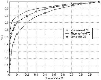
To calculate the void three known slip correlations; Kirilov, Thoms and Zivi were used. The authors reached different results indeed, however this does not influence the conclusions of this paper. (Figure 3).
Figure3. Comparison between different void correlations as a function of steam quality
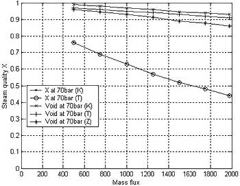
The most important result is, that at the onset of the excessive surface temperature the void value changes merely between 0.88 to 0.99, while the steam quality changes in a wide range from 0.45 to 0.75 (Figure 4)
Figure 4. Void and Steam Quality as a Function of Mass-Flow at the Onset of the Abrupt Surface Temperature Increase
There has been knowledge of this, however - according to this author’s but this has not been explicitly outlined. This helps to focus on the void when planning further test loop experiments, as well as when monitoring the safety of operating reactors and when designing new fuel assemblies. By using the constraitns described here -limiting the permissible void content - damage of the fuel can be avoided.
6. AVOIDING EXCESSIVE FUEL TEMPERATURE
The awareness of this result helps the design of a tool to avoid excessive
fuel surface temperature and clad failure in operating reactors. To monitor
the void during operation is presently not feasible, however from the measured
parameters, power, power distribution, coolant flow, pressure etc. the steam
quality everywhere in the core can be calculated continuously and the void
can be deduced using steam quality versus void correlation derived from loop
experiments. It is interesting to note that an analytical model is described
in the literature. The mathematics is applied for a Freon loop and the deduced
figures coincide with the measurements from the experimental loop mentioned
above. The results are summarized in Figure 5. The abrupt increase of the temperature
here too occurs when the void value reaches around 90% for a wide range of
subcooling.
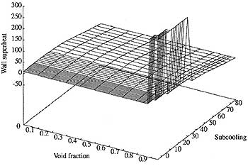
Figure 5. Prediction of critical heat flux
for Freon at p=1.5 bars, q ”= 190 kW/m2 at constant liquid
velocity of 0.5 m/
7. CONCLUSIONS
A series of experimental investigations on the maximum permissible power production
of Boiling Water Reactors (BWR) and the effect of it on the fuel element’s
surface temperature was performed at the test facility located at KTH, Royal
Institute of Technology in Stockholm, Sweden. The results show that the “void” is
the principal parameter for defining the onset of the excessive surface temperature
phenomena leading to burnout of a fuel rod.
![]()
© European Nuclear Society, 2008