

The GUINEVERE experiment: a first step on the road to MYRRHA
As mentioned in ENS N° 21 (summer 2008), SCK•CEN (the Belgian Nuclear Research Centre) is a candidate for hosting a European fast-spectrum experimental facility for demonstrating efficient transmutation and associated technologies using a system that works in sub-critical and/or critical mode. With this in mind, SCK•CEN started, in 1998, designing the MYRRHA facility as an accelerator-driven system (ADS) with the following objectives:
-
To demonstrate ADS technology, full-scale, within the framework of research into the transmutation of high-level radioactive waste
-
To serve as a flexible fast-spectrum irradiation facility for testing materials and innovative fuels for ADS and GEN IV systems and fusion reactors
-
To contribute to the technological demonstration of the GEN IV Lead Fast Reactor
-
To perform fundamental and applied physics research making use of SCK•CEN's high-power proton accelerator
As a first step towards the development of MYRRHA, the GUINEVERE project (Generator of Uninterrupted Intense NEutrons at the lead VEnus REactor) was launched. GUINEVERE is part of the EUROTRANS Integrated Project (6th EURATOM Framework Programme). EUROTRANS collects feasibility and design studies for an ADS demonstrator, as well as its possible extension for use in an industrial transmutation installation. GUINEVERE aims to provide a zero power experiment which will investigate online reactivity monitoring and absolute reactivity measurements, both of which are major issues for ADS safety.
To do so the VENUS reactor of SCK•CEN (at Mol) will be coupled to a neutron source driven by the GENEPI-3C deuteron accelerator. This accelerator will not only be operated in pulsed mode, but also in continuous mode, the latter being the more representative of a powerful ADS. Thanks to the flexibility of the GENEPI accelerator VENUS will provide a unique facility in Europe where it will be possible to investigate both fast-critical and subcritical reactor.
The VENUS reactor was a zero power thermal critical mock-up until 2007. From then on it has been dedicated to the GUINEVERE experimental programme and, therefore, it had to be changed into a lead fast reactor called VENUS-F.
The VENUS-F core will consist of fuel assemblies (FA) arranged in a cylindrical geometry of ~80 cm in diameter and 60 cm in height. Each FA is composed of a combination of round fuel rodlets and of square solid lead rodlets which constitute a fast system coolant. These rodlets are arranged in a 5x5 pattern. Lead plates are added around the pattern in order to decrease the fuel/coolant ratio (and hence to increase the core size). In total a FA is 80 mm wide. A cross section is shown in fig. 1. The fuel is provided by CEA, and it consists of 30%
235U enriched metallic uranium. The core is expected to become critical with 88 FA's installed.

Fig. 1: Cross section of the FA pattern chosen for the VENUS-F core:
Yellow circles: fuel rodlets; green squares: lead.
The core will be surrounded by two 40 cm axial and radial lead reflectors. At the centre of the core a channel can be arranged with a stainless steel shaft for the insertion of the final part of the accelerator beam line, including the target and its cooling system. In order to allow for sufficient space, but keeping the simple and symmetric geometry, this channel is chosen to have the cross section of 4 standard FA’s. A small lead buffer is foreseen to fill the gap between the target tube shaft and the 160x160 mm2 central hole. Fig. 2 shows a radial view of the reactor at its mid-plane (only the inner parts of the vessel are shown), in a configuration with 84 FA's and keff ~ 0.97.
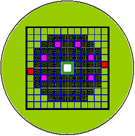
Fig. 2: Cross section (mid-plane) of the sub-critical core configuration (84 FA’s).
A new shut-down system had to be implemented for the fast neutron reactor. It is based on the standard philosophy of safety rods falling in the core under the influence of gravity when the signal for de-energizing the electromagnets is received. The safety rods consist of a neutron absorbing material (B4C with natural boron), 60 cm long, and it features a fuel follower which has the same pattern as shown in Fig. 1. When a safety rod is up its fuel follower reaches the height of the core, thereby eliminating core perturbations; when a safety rod drops an anti-reactivity is inserted by the combined effect of removing fuel and inserting absorber material. In total 6 safety rods are foreseen at fixed positions in the core. The control rods on the other hand only contain an absorber part that slides inside a wrapper tube. Their number and the choice of their position are flexible. A typical configuration is shown in fig. 2.
The accelerator beam access was chosen to be vertical in order to preserve the cylindrical symmetry. But due to the small size of the reactor (160 cm in diameter) it was not possible to host the accelerator at the reactor top level. Therefore, the VENUS reactor building had to be modified by adding a dedicated room for the accelerator at an upper level (see Fig. 3). Civil engineering work at the VENUS building was started on September 1, 2008, and it was completed at the beginning of March 2009. Electrical power equipment and ventilation systems will be ready by the end of the summer 2009, and the accelerator will be installed from September 2009 onwards.
The accelerator called GENEPI-3C (GEnérateur de NEutrons Pulsé Intense-3Continu) is the third of a series that is explicitly foreseen for neutron experiments. It has been designed and built by a CNRS/IN2P3 (France) partnership and is being assembled and fully tested at the LPSC in Grenoble. Full commissioning and the beam characterization at the final target will be ready by the summer 2009. After that it will be disassembled for transportation to SCK•CEN in Mol, and reassembled in the VENUS-F reactor building.
The machines of the GENEPI family are 250 kV electrostatic accelerators. They are fitted with a duoplasmatron ion source, and they deliver a deuteron beam to a copper target with a titanium-tritium (TiT) or a titanium-deuterium (TiD) deposit. In this way they provide 14 MeV or 2.5 MeV neutrons via the T(d,n)4He or D(d,n)3He reaction, respectively. The first GENEPI acceleator was designed for the MUSE experimental programme at the MASURCA reactor (CEA Cadarache, France, 2000-2004). It operated in pulsed mode only, with a peak
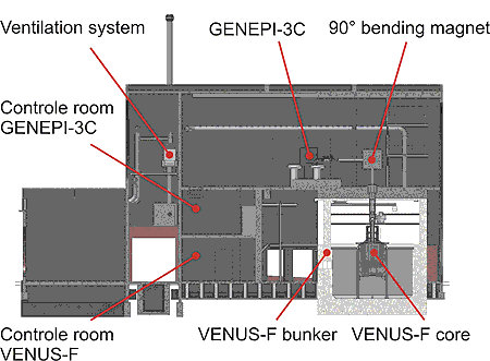
Fig. 3: Side view of the modified VENUS facility.
current in the pulse of 50 mA and a pulse length of the order of 1 ms. The new GENEPI-3C machine repeats these specifications and adds a continuous mode, with a maximum DC beam current of 1 mA. Furthermore, it will be possible to generate programmable beam interruptions with steep falling and rising times in a flexible way.
A general layout of the machine with its supporting structures is shown in fig. 4. The vertical beam line, ended by the target, is obviously partly inserted in the reactor. In order to exchange targets and for beam line maintenance, but also for reactor maintenance and reconfiguration, the entire vertical beam line must be removed. So, it is necessary to raise this beam line, which is fixed in a dedicated support structure, up to a level above the floor of the accelerator room. This is achieved by means of a crane and adequate guiding tools. Upon arrival in the accelerator room it is then stored in a stand and surrounded by working platforms. To allow for this operation the 90° bending magnet gets displaced over 2 sliding rail tracks.
The GUINEVERE experiment will make important contributions to the fields of calculation code validation for ADS applications and to the methodology for online reactivity monitoring in an ADS. The main issue here is the validation of the direct relation between the beam intensity and the power level of the reactor as an online reactivity indicator. The corresponding experimental programme has been fixed within the EUROTRANS collaboration,
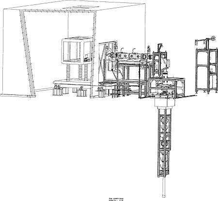
Fig. 4: General layout of the GENEPI-3C machine with its supporting structures.
and consists of 2 phases. In the initial phase the VENUS-F reactor will be operated and fully characterized in its critical mode, so as to provide a solid reference for the subsequent ADS experiments. The second phase then uses the subcritical configuration and the coupling to the accelerator using a tritium target. During this phase 3 types of experiments are planned, each type corresponding to a specific time structure of the deuteron beam and thus of the neutron source. In order to relate to the earlier MUSE experiments the pulsed beam is used with a pulse length of around 1 ms. After the pulse the time evolution of the neutron population in the core is recorded, and its analysis yields an estimation of the reactivity. Then, in a second experiment, this method is applied to a situation in which the time structure of the beam is basically continuous but with interruptions at regular intervals. The "beam on" periods are chosen long enough to reach a steady state situation. The "beam off" interruptions may be chosen as either short (around 200 ms, see fig. 5) or long (around 2 ms), corresponding to 2 distinct ways of analysing the decay of the core neutron population and obtaining the reactivity. Finally, the true continuous beam will be used at several levels of current in order to obtain the relationship between beam intensity and neutron flux, and to validate this method as a truly online reactivity measurement for ADS applications.
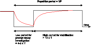
Fig. 5: The principle of prompt decay signals at a short beam interruption (black: beam current, red: neutron flux).
Contacts:
Dirk Vandeplassche (dirk.vandeplassche@sckcen.be)
Peter Baeten (peter.baeten@sckcen.be)
www.sckcen.be
|


