
European
Nuclear Society
e-news
issue 48: May 2015
Dear Reader,
For the past ten years I have had the great pleasure and honour to have been Editor-in-Chief of ENS NEWS. However, as the saying goes, ‘all good things must come to an end,’ and I have decided to retire and call time on a career that has spanned over thirty-five years. ENS will now set about appointing a new Editor-in-Chief.
I would like to take this opportunity to sincerely thank you all - readers and contributors - for the great support that you have given to ENS NEWS during this period, and especially for putting up with the hundreds of editorials, articles and reports that I have either edited or written for you over the years. I hope that you have found reading them to be a useful, informative and enjoyable experience. As someone who is not from a nuclear science or engineering background (I’m sure that fact will not have escaped you!), I have always found editing ENS NEWS to be a very challenging, educational and stimulating experience; a lengthy collaboration that I will always remember fondly.
Finally, I would like to wish you all the very best for the future!
Best Regards,
|
|
http://www.euronuclear.org/e-news/e-news-48/presidents-contribution.htm

ENS conferences are important events for our members. They are a focal point where they meet and exchange their expertise and their latest results in the field of nuclear sciences, as well as general news about all things nuclear. On April 22, I attended the final sessions of the RRFM conference (Research Reactors, Fuels and Materials) in Bucharest. Since questions had been raised by the IAEA about the connection between research reactors and their end users, I spoke about the value of such important research facilities to a major nuclear operator like us at EDF. Allow me to quote my own words:
|
“As a major nuclear operator, we use research reactors in France and also in Europe. Sometimes we even go to other continents to use them. I was glad to hear Dr. O’Kelly from Idaho National Lab this morning. We do not use the ATR reactor and the associated fuel cells directly, but we use them through the EPRI Research Organization, of which we are a recognized international member. |
We use research reactors first for fuel qualification. Even though this was only one of the items in the table presented by Dr. Ridikas from IAEA, for us it is an important one. We perform load following on the French nuclear fleet and we have a special regulation for pellet cladding interaction (PCI), which we can only fully be qualified in research reactors. We also load MOX fuel in our 24 900 MW units, which are licensed for MOX and we like to be able to perform special measurements for such fuels, even though in an international programme UOX fuel will be the primary interest for most of the other industrial partners.
Of course, we also use research reactors for materials irradiation and qualification. It is no surprise that we spoke at the conference with AREVA about the non-occurrence of flakes in our reactor pressure vessels and, therefore, of the absence of embrittlement problems that potentially arise from such hydrogen flakes. We also gave details about ultrasonic measurement techniques and hydrogen degassing techniques in French steel warehouses. If you follow French media, steel fracture toughness in all kinds of forged steels has become a heated topic.
I am very glad that I came to Bucharest. I could only fully follow 2 sessions, one chaired by Dr Gerstenberg from München, if I remember correctly, and the other by Edgar Koonen, the Program Committee Chairman on International Issues. They were very good sessions, and I learned many things, for which I thank the speakers and the organizers. Research reactors in Europe are important for the nuclear scientific community, and also for the larger industrial community. This is why we believe that your community should be helped and supported.
Thank you”.
Noël Camarcat
President of ENS
http://www.euronuclear.org/e-news/e-news-48/floride-salt-htr.htm
David M. Carpenter, Michael Ames, Yakov Ostrovsky, Gordon Kohse, Lin-wen Hu
Nuclear Reactor Laboratory
Massachusetts Institute of Technology
Abstract – The first irradiation test of structural materials and surrogate TRISO fuel particles in a molten, fluoride-based salt was completed successfully at the Massachusetts Institute of Technology Research Reactor (MITR). The irradiation test is part of an ongoing joint research program being conducted at MIT, the University of California-Berkeley (UCB), and the University of Wisconsin-Madison (UW). The objective of the overall research program is to develop a path forward to a commercially viable, fluoride-salt-cooled, high-temperature reactor (FHR). The baseline FHR concept combines a fluoride salt coolant called flibe (a mixture of LiF and BeF2), with a graphite-matrix, coated-particle fuel. The objectives of the first FHR irradiation experiment at the MITR are: (1) to assess the corrosion and compatibility of 316 stainless steel, Hastelloy N®, SiC and SiC/SiC composites, and surrogate TRISO fuel particles in molten flibe, and (2) to examine the partitioning of tritium (produced when the flibe is subjected to neutron irradiation) among the various media in the experiment. This irradiation was performed with flibe temperature at 700°C which marks the first demonstration of flibe irradiation capability at the MITR. Initial results provide evidence of the high potential mobility of tritium in an FHR system consisting primarily of liquid flibe, graphite, and high-nickel alloys at high temperature. At the same time, a large percentage of the tritium that was predicted to have been generated in the salt was not detected in the gas phase, mirroring experience from the MSRE and indicating a potential for tritium control through tritium capture in solid components. Fast neutron activation products 16N (t1/2 = 7.1 s) and 19O (t1/2 = 26.9 s) were measured and shown to be significant radiation dose contribution in the gas phase. Post-irradiation examination of irradiated materials is ongoing and will attempt to identify if the tritium balance can be accounted for by tritium absorption in the salt, the specimens, and the capsule’s structural materials. Measurements of the corrosion rates of SiC, SS316, and Hastelloy N coupons has shown that all three are susceptible to some corrosion in the salt, with higher rates when coupled with nuclear-grade graphite. In addition, surrogate TRISO particles exposed directly to flibe appear to have increased susceptibility to radial cracking after irradiation and salt freeze-melt cycling.
The Fluoride-Salt-Cooled High-Temperature Reactor (FHR) concept is the subject of an ongoing three-year U.S. Department of Energy-funded Integrated Research Project (IRP), which aims to develop the “path forward” to a salt-cooled test and commercial power reactor. This IRP is led by the Massachusetts Institute of Technology (MIT) in partnership with the University of California, Berkeley and the University of Wisconsin-Madison (UW).1
The FHR baseline concept is a fluoride-salt-cooled, graphite-moderated pebble-bed reactor with 600°C inlet and 700°C outlet coolant temperatures. The lithium-beryllium fluoride salt primary coolant (67%LiF-33%BeF2), known as flibe, was chosen because of its favorable characteristics as a high-temperature, low-pressure heat transfer fluid that is optically transparent and has good neutronics properties.
The FHR concept is based on experience from the Molten Salt Reactor Experiment (MSRE), which operated at Oak Ridge National Laboratory (ORNL) between 1964 and 1969.2 The MSRE used a fueled salt in its primary loop (ZrF4-UF4 was added to the flibe). In contrast, the FHR takes advantage of recent coated particle fuel (TRISO) technology to provide compatibility between TRISO/graphite fuel compacts and the liquid flibe, isolate the fuel from the salt, and maintain a “clean” primary coolant.3
The combination of flibe coolant, TRISO compact fuel, and a graphite core structure allows the FHR to achieve a large thermal margin to core damage. The boiling point of the flibe is 1430°C, and the failure temperature of the graphite and TRISO particles is above 1600°C. With an outlet temperature of 700°C the FHR has a substantial temperature safety margin compared to existing light water power reactors.
Proposed materials for other structural components of the FHR design are 316 stainless steel (SS316), Hastelloy® N, carbon-fiber composites (CFCs), and silicon carbide fiber composites (SiC/SiC). Hastelloy N was developed specifically for use with liquid salt and has excellent corrosion resistance at the temperatures of interest, as was demonstrated in the MSRE. However, as a specialty metal Hastelloy N has limited commercial production and is not code-qualified as a vessel structural material for reactor operation at FHR conditions. Therefore this IRP is investigating the possible use of SS316 as a well-characterized and economical replacement. CFC and SiC/SiC materials have seen substantial development and improvement in quality in the last few decades, with increasing interest in their use in both fusion and fission reactor environments. In the FHR, these ceramics are being considered for the core barrel and as control element and instrumentation channel liners, which are structures in high-radiation areas that do not need to be as stringently code-qualified (e.g. are not classified as pressure vessels).
An irradiation test including the flibe and proposed FHR structural materials has been designed, built, and carried out at the MIT Nuclear Reactor Laboratory (MIT-NRL) utilizing the MIT Research Reactor (MITR). The purpose of this irradiation was threefold: (1) to demonstrate the ability to implement a flibe-bearing materials test at 700°C in the MITR; (2) to measure the transport and disposition of tritium produced in the flibe; and, (3) to evaluate the corrosion of TRISO and FHR structural materials exposed to flibe at 700°C during neutron irradiation.
The MIT test was carried out at the NRL in parallel with non-irradiated autoclave tests which took place at UW. The UW and NRL tests utilized an identical test matrix with the specimens and specimen holders sourced from the same materials and prepared at the same location. The main purpose of these initial parallel tests is to isolate the effects of irradiation damage and other irradiation-induced effects such as tritium generation on the test results and to help to determine what further irradiation experiments are required for initial FHR development.
Furthermore, this irradiation represents the first attempt to irradiate significant amounts of flibe under active temperature control at the MITR.
The MITR is a 6 MW, light water-cooled, heavy water-reflected tank-type research reactor. The MITR has a compact, HEU core with plate-type fuel in rhomboidal assemblies arranged in three concentric rings. Of the 27 in-core element positions, three (two in the central ring, one in the middle ring) are dedicated for in-core experimental facilities. The neutron flux available to experiments in-core is up to 3.6x10¹³ n/cm2-s thermal and 1.2x10¹⁴ n/cm2-s fast (E>0.1 MeV) when the reactor operates at full power, with a spectrum similar to that of a light-water reactor.
The MITR’s primary coolant is light water at atmospheric pressure and an outlet temperature of about 50°C. The free space available in-core for a single experiment is approximately 5 cm in diameter and 56 cm in height. These constraints require the use of special facilities in order to achieve the desired test conditions. For this initial irradiation the target conditions are a constant 700°C exposure for 1000 hours under inert cover gas.
The irradiation utilized the In-Core Sample Assembly (ICSA) facility installed in one of the central-ring core positions. The ICSA is a general-purpose irradiation facility, which has been approved and demonstrated for capsule irradiations up to 900°C.4 The ICSA outer thimble is a titanium tube with a 5 cm outer diameter and S-bend shape that extends from just below the reactor top shield lid, four meters down to the bottom of the core. The S-bend shape prevents direct radiation streaming up through the core tank. Connections at the top of the thimble and integral gas lines along its side allow for gasses to be continuously injected into the ICSA at the bottom of the core and exhausted from the top of the thimble. Experimental test components in the ICSA are contained in metal capsules that are inserted from the top of the ICSA. ICSA capsules are typically about 4.5 cm in diameter and 15 cm long. Several different capsules can be stacked within the in-core region.
Heating in the ICSA is accomplished passively, primarily utilizing gamma heating of high-Z materials. Heat is rejected from the system across the gap between the capsules and the thimble, and then into the MITR’s primary coolant. Through careful design of the irradiation capsules and radial gas gaps, temperatures of up to 900°C are readily achievable. While the gross ICSA capsule temperature is controlled by reactor power and capsule design, fine control of temperature is achieved by varying the gas mixture in the thimble. To operate the ICSA at the lowest temperature, the thimble is filled with 100% helium; in order to increase temperature, neon (which has a lower thermal conductivity than helium) is added. The demonstrated temperature control range that can be achieved by varying the helium/neon mixture is about
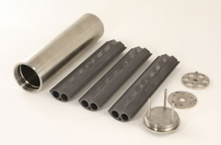
Fig. 1. Components of the experiment capsule prior to assembly. Left-to-right are the outer nickel capsule, the three sections of the graphite sample and flibe holder, and, top-to-bottom on the right, the bottom graphite support/spacer, the top cover plate, and the capsule lid (without thermocouples and gas lines).
450°C as demonstrated during ICSA testing at 5 MW, although this will vary somewhat depending on the absolute temperature and capsule geometry.
The irradiation capsule for this experiment, components of which are shown in Figure 1, was designed to meet the experiment’s thermal requirements, allow independent sampling of the capsule and thimble gases, and protect the ICSA from exposure to the salt or its corrosive byproducts. The outer capsule was constructed from Alloy 201 nickel except for the top threaded section and lid which are Inconel® 800H. These materials were chosen for their high-temperature strength and resistance to flibe and HF corrosion. HF may be produced from the flibe if it comes into contact with moisture or as a result of tritium generation (TF). These metals also provide a good susceptor for gamma heating of the capsule internals and are sufficiently resistant to neutron irradiation for the purposes of the 1000-hour test.
Inside the capsule is a three-section graphite sample holder, shown in the center of Figure 1, machined from IG-110U, a high-purity, isotropic graphite manufactured by Toyo Tanso. The graphite provides compatibility with the flibe, excellent thermal conductivity (providing a uniform temperature distribution), and is part of the test matrix for corrosion and tritium interactions. There are six vertical chambers machined into the graphite, 1 cm in diameter and 14.5 cm deep, where the salt and specimens reside. A nickel disk rests on top of the graphite and a thin nickel base plate supports the graphite above the bottom of the capsule. This arrangement is designed to produce a small vertical temperature gradient in the capsule, ensuring that
TABLE I
Specimen Test Matrix
Graphite Chamber |
Liner |
Specimens |
A |
none |
2 Hastelloy N plates |
B |
none |
2 SS316 plates |
C |
none |
3 SiC/SiC, 1 SiC |
D |
none |
~300 TRISO particles |
E |
SS316 |
2 SS316 plates |
F |
Hastelloy N |
2 Hastelloy N plates |
the salt melts from the upper free surface downwards to prevent damage to the graphite holder from flibe expansion during the phase transition.
The capsule’s lid has penetrations for two gas tubes and three nickel rods (all Inconel 600). The gas tubes allow the helium cover gas in the space above the flibe to be sampled and refreshed. The nickel rods were brazed into the lid and extend down into the graphite holder; their extra mass is used to assist with melting the flibe from the top down. Thermocouples run through two of these rods, and the thermocouple tips sit in the graphite at the half-height of the capsule between chambers. The lid threads into the lower capsule and seals it by compressing an Inconel 718 C-ring.
The specimen test matrix is given in Table I. Two of the chambers, E and F, were lined with metal – the flibe and specimens in these chambers are not exposed to graphite. All of the metallic specimens are rectangular coupons (25 mm x 6mm x 0.5 mm), which hang on wires made from the matching metal and are secured through small holes in the nickel disk above the graphite. The SiC and TRISO specimens sit freely at the bottom of their chambers.
Assembly of the capsule took place in three main steps. First, the capsule parts were manufactured from nickel and graphite, and the gas tubes, thermocouples, and nickel pins were brazed into the capsule lid.
Second, the loading of the flibe and specimens into the graphite chambers was performed inside an argon-filled glove box at UW using the same process and equipment used to load the flibe and specimens for the parallel UW autoclave test. Immediately prior to the loading the graphite sections and liners were heated at 800°C in an argon-10%-hydrogen atmosphere for 24 hours. This process removes oxygen and moisture that may be adsorbed on the surfaces of the components – such a surface preparation process is important for any equipment to be used with liquid flibe. After all of the specimens were placed in the graphite chambers, flibe was dripped slowly into each chamber directly from a heated storage container until the chamber’s target mass was achieved. The flibe loadings in each chamber are given in Table II.
After loading the specimens and flibe into the chambers, the graphite was inserted into the nickel capsule, the capsule was closed with a temporary blank lid, and the closed capsule was then sealed into a secondary container for shipping back to MIT. All of sealing at UW was done inside an argon-filled glove box.
Final assembly took place at MIT. The capsule, with temporary lid, was placed in a circulating helium-filled glove box where the lid was removed. The full capsule was held at 250°C for five hours before the final lid (with thermocouples and gas lines) was sealed on. The capsule was then inserted into the ICSA tube in the reactor and immediately connected to gas lines for helium purging while cold.
A neutronics analysis of the ICSA experiment was performed using the MCNP-5.1.4 code and a 3D representation of the MITR core. This calculation predicted axial-average neutron fluxes of 2.35x10¹³ n/cm2‑s thermal and 1.16x10¹⁴ n/cm2-s fast (E>0.1 MeV) in the salt chambers with the reactor at a power of 6 MW. Using this code the gamma heating rates of the graphite and nickel structural materials in the capsule and the titanium ICSA tube were also estimated. These data were fed into the ANSYS Fluent v13 computational fluid dynamics code for calculation of the temperature distribution inside the experiment. This process was used iteratively during the design phase to fine-tune the proper dimensions for the capsule wall in order to achieve the target 700°C in the salt chambers.
For the Fluent analysis, a 3D capsule model and a 13-inch high section of the ICSA tube was converted and meshed using the ANSYS meshing tools. This analysis modeled the flibe physically as a solid with the thermal properties of the liquid at 700°C. It also considered the gas flow in the outer ICSA tube, but not within the capsule (the capsule gas space was modeled as a heat sink, removing the small amount of energy calculated to be lost to the cold helium flowing at 50 cc/min). The initial analysis considered two extreme conditions for the outer ICSA thimble gas with the reactor operating at 5.9 MW: (1) 100% helium gas flow, and (2) 100% neon gas flow (both at 100 cc/min). In both cases the capsule internal gas remains pure helium. The simulation results are shown in Figure 3; the maximum predicted temperature in the sample chambers is 760°C with 100% helium and 1130°C with 100% neon.
TABLE II
Flibe Loading
Graphite Chamber |
Flibe Mass (g) |
A |
21.3 |
B |
21.2 |
C |
21.2 |
D |
21.2 |
E |
18.2 |
F |
18.1 |
The flibe salt used in the MIT irradiation and the UW autoclave test was procured from Oak Ridge National Laboratory. This salt is from the supply of flibe for the secondary coolant loop of the MSRE and has been in storage since that reactor’s decommissioning. The flibe used in the primary and secondary systems of the MSRE was enriched in 7Li because of the unfavorable 6Li(n,α)3H reaction, which has a large, 940 b thermal cross section. 6Li, which is 7.5% abundant in natural lithium, is therefore both a neutron poison and a substantial source of tritium. To counter this, the MSRE utilized 99.995% 7Li enriched flibe in its fueled primary loop, and 99.99%
7Li enriched flibe in its clean secondary loop and flush systems.5 However, even if 6Li were removed entirely from the flibe, an equilibrium level of 6Li will be reached due to generation from the 9Be(n,α)6He reaction, so flibe will always be a significant tritium generator. Smaller amounts
of tritium are also produced in flibe by the 19F(n,t)17O and 7Li(n,n+t)4He reactions.
Flibe must be handled carefully and kept in a dry, inert environment as the salt will readily absorb moisture. It is a strong oxidizer, and will react with metal oxides (e.g. surface layers) to form metal fluorides. At elevated temperatures the salt will decompose in the presence of H2O to form HF and BeO.6 In turn, if the HF becomes hydrated, it will form hydrofluoric acid that can easily etch glass and steel surfaces.
The salt from the MSRE has been stored at ORNL in sealed steel containers for over 40 years. This, combined with our assessment that there may have been little or no chemical cleanup of the MSRE secondary system (metal corrosion product buildup was detected during reactor operation), presented the possibility of contamination of the MSRE flibe with various trace elements. It is likely this MIT irradiation represents the first time this enriched flibe has been analyzed, or irradiated, since the 1960’s.
The flibe used in this experiment was transferred at ORNL into smaller stainless steel containers using a heated, sealed, and pressurized loading system, and then shipped to UW. At UW the salt was re-melted and extracted from the shipping container, and then purified to remove moisture and oxides and to reduce the presence of trace metals. In short, the flibe was first melted in the presence of metallic beryllium and sparged with argon and hydrogen gasses. Next, a 1:10 by volume mixture of hydrogen and hydrogen fluoride gas was bubbled through the liquid salt for 1.5 hours, followed by 24 hours of sparging with H2. Samples of the flibe before and after this purification were sent to the MIT-NRL for neutron activation analysis (NAA). Although there was no explicit salt purity standard in place for this experiment, the original impurity standards for the MSRE primary flibe were used as
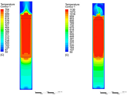
Fig. 2. Fluent calculation of experiment capsule with (left) 100% helium thimble gas, and (right) 100% neon thimble gas at 5.9 MW reactor power.
a point of reference. The NAA analysis found that the UW purification process did help to reduce the amount of trace metals in the flibe; however, levels of Al and Cr remained slightly above the MSRE impurity standard (173±19 ppm vs. 150 ppm Al and 36±1 ppm vs. 25 ppm Cr), and levels of manganese and nickel are still undetermined.7
Other than this initial purification and NAA, there was no active effort to control or monitor the redox potential of the flibe during the experiment. This was done in part because the optimum redox potential for the FHR had not yet been decided, but this also allowed design simplification for this initial demonstrative irradiation (and the parallel UW tests).
The ICSA and experiment capsule were installed in the MITR on September 10, 2013. A schematic of the ICSA gas system for this test is shown in Figure 4. The basic layout consists of three parallel gas supply systems regulated by mass flow controllers – one helium and one neon system to the ICSA thimble, and one helium system to the experiment capsule (the emergency helium system floods the thimble in the event of an over-temperature condition). The main helium gas flows are intended to be constant during the experiment; the neon mass flow into the thimble, however, is generally controlled manually or from a PID temperature controller that receives feedback from one of the two capsule thermocouples (TC 1). Because of the sensitivity of the flibe to contamination, an oxygen gettering furnace with a zirconium element is used on the helium supply gas to the capsule to help remove any traces of oxygen. Gas pressure is monitored at the inlet to the ICSA tube and capsule independently on the helium and neon lines, and controlled with a backpressure regulator at the outlet of the thimble and capsule. Helium and neon are supplied independently and mixed at the bottom of the ICSA thimble in order to decrease the response time between adjusting the neon flow rate and achieving a change in the gas mixture in the in-core section.
The outlet gas from either the thimble or the capsule can be directed through a train of instruments including a Dycor® LC Series residual gas analyzer (RGA), Overhoff Technology Corp. TASC tritium bubbler, and Omega Engineering Inc. PHE-4201 pH probe contained in a dedicated water bubbler. The exhaust gas is then directed through a charcoal filter before being mixed into the reactor building’s ventilation system for monitoring and exhaust. The experiment exhaust line not being monitored by the instrument train runs directly into the charcoal filter.
After installation of the capsule into the ICSA thimble the gas system operated at ambient temperature and 100 cc/min helium gas flow through the thimble (100 kPa) and capsule (135 kPa) for three days in order to remove air and moisture before heating the capsule. Levels of both air (monitored as nitrogen) and water were evaluated using the RGA on the gas exhaust system.
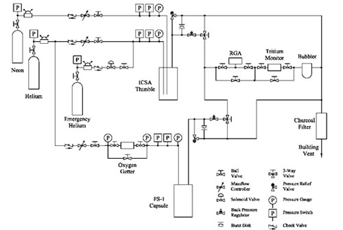
Fig. 3. Schematic layout of the ICSA gas system with the experiment capsule (labeled FS-1).
On September 13 the reactor was started and its power was raised in 500 kW steps with 20 minute stabilization periods up to a power of 2 MW, at which power the capsule temperatSure reached 290°C. The temperature was held there to allow any additional moisture to be evolved from the system.
While holding at 2 MW, a higher than expected level of radioactivity was observed near the capsule outlet tubing. Analysis of the radiation’s gamma spectrum using a portable HPGe detector (Canberra Falcon 5000®) determined the primary contributors to be 16N (t1/2 = 7.1 s, primary Eγ = 6.129 MeV) and 19O (t1/2 = 26.9 s, primary Eγ = 197.1 keV and 1.357 MeV). These isotopes were being produced from fast neutron reactions on 19F ((n,α) and (n,p), respectively) and were then escaping the flibe into the capsule cover gas. It was not clear if the rate at which these gases were being released at this time was controlled by reactions at the salt’s free surface or by diffusion through the solid (though possibly porous) flibe. On September 16 reactor power was briefly lowered to 50 kW for adjustments to the capsule exhaust line. The length of exposed tubing in the capsule gas outlet line was reduced, a radiation monitor (GM tube) was placed immediately next to it, and a delay volume surrounded by 8 inches of lead shielding was installed.
It is interesting to note that the production of 16N and 19O in the flibe was not mentioned in the ORNL reports on their MSRE experience, likely because of both the short half-lives of these isotopes and the presence of many other highly radioactive fission products in the MSRE primary salt. In contrast, this experiment’s salt contained few other radioisotopes. Also, the sweep gas transit time from the reactor core to the measurement location was on the order of one second. These isotopes were not detected in the ICSA thimble exhaust gas because: (1) they have no ready path into the thimble gas space, and (2) if they were present in-core, the transit time through the upper portions of the thimble is on the order of ten minutes. It should also be noted that while 16N and 19O isotopes are produced in water-cooled reactors (from neutron reactions with stable oxygen isotopes), on a curies per gram coolant basis, the production of 16N is hundreds and of 19O thousands of times higher in flibe than in H2O (calculated using ORIGEN-S with the MITR neutron spectrum).
On September 17 reactor power was again increased in 500 kW steps. At 3.5 MW reactor power was held and the capsule temperature reached 425°C. Neon was then introduced into the ICSA thimble to slowly raise the capsule temperature through the flibe melting point (459°C). The ICSA gas system was held at 20 cc/min neon, 80 cc/min helium with the capsule at 470°C before reactor power was again increased in 500 kW steps. At 5.5 MW the capsule reached 640°C; helium flow was decreased and the neon flow was manually increased before regulation was turned over to the automatic PID controller. With a helium flow of 60 cc/min, the neon flow rate settled at 32 cc/min in order to hold the capsule temperature at 700°C.
As shown in Figure 4, the experiment ran without interruption and at constant reactor power for the next 1000 hours, with variations in the controlled neon flow rate of ±2 cc/min and temperature of ±1°C from one thermocouple and ±3°C from the second, noisier thermocouple (this noise may be in part due to the first thermocouple being transmitted as a voltage and the second as a current loop).
Temperature, pressure, and flow rate data were monitored at 2 Hz by the data acquisition system, while RGA data was taken approximately once per minute and tritium samples were collected for 24 to 72 hours between exchanges.
While the reactor power remained constant, the capsule gas mass flow rate also remained constant. Only 16N and 19O were definitively measured in the capsule outlet gas (41Ar was also detected in the gas, presumably due to activation of trace argon in the helium supply, but it was difficult to distinguish from low levels of 41Ar normally present in the MITR containment building during reactor operation). The activity level of the capsule outlet gas, however, varied significantly as measured by the GM tube at the capsule gas outlet line. After rising during the reactor power increase to 2 MW, the activity peaked and then gradually decreased; it was reduced by a factor of 10 by the morning of September 16th. There were no substantial changes to the observed activity between the restart to 2.5 MW and reaching 5 MW despite passing through the flibe melting point. The activity increased sharply after reaching 5 MW, then decreased slowly over the next five hours after a similar increase at 5.5 MW. It then slowly increased over the following four days by a factor of three to its highest recorded value on September 21st (double the previous peak achieved at 5 MW). After this point it decreased linearly over time while the capsule gas was being monitored.
The mechanisms behind this variation in the release of the gaseous activation products is not clear, however it may be related to a second observed phenomenon. During the afternoon of September 24 the capsule pressure suddenly began rising, requiring a gradual decrease in the capsule inlet gas flow to stabilize the pressure. Within 16 hours of the first pressure rise, flow to the capsule had to be shut off completely to keep the inlet pressure from increasing. It is postulated that the capsule outlet gas line became constricted due to a buildup of some material from the capsule. The most likely source is volatilized BeF2, which has a higher vapor pressure than LiF, and could preferentially condense on the walls of the colder 1.6 mm diameter outlet gas tube.8 By momentarily redirecting the capsule inlet line from the helium supply to the charcoal filter vent to reduce the pressure in the capsule, it was demonstrated that 16N and 19O activity could be vented from the capsule, indicating that the inlet gas line was still communicating with the capsule internal gas space. From this point forward the capsule was held at 100 kPa with a static helium supply, however no further sampling of the capsule gas (RGA and tritium) was possible. After two weeks of operation in this mode the activation products were not observed during the attempted depressurization. Although this pressure testing continued twice weekly for the remainder of the experiment, it is assumed that at that point

Fig. 4. Capsule temperature vs. reactor power over the irradiation. Differences in placement in the ion chambers used to record reactor power for the experiment result in readings slightly shifted from the official control value but respond more promptly to power changes.
both the inlet and outlet lines had become constricted with the unknown material, and communication with the capsule internal gas space was not reestablished.
The experiment reached 1000 hours at temperature on the morning of October 29, and the reactor proceeded to reduce power in 500 kW steps with 10-minute stabilization periods at each step down to a reactor power of 2.5 MW. In a reverse of the startup procedure, with the capsule temperature starting at 500°C, neon flow was gradually reduced to zero.
Following the irradiation, the nickel capsule was transferred to a shielded hot box for disassembly. The capsule lid was unscrewed, and the three graphite wedges were extracted and transferred to individual helium-purged containers. During the lid removal it was found that the graphite sections were unable to rotate, possibly due to larger-than anticipated swelling or deposition of volatiles, and therefore there was minor damage to the tops of the chambers above the frozen salt as the thermocouples and nickel pins were removed.
Each graphite section was then moved to a helium-filled glove where it was baked in a ventilated furnace at progressively higher temperatures to remove any moisture. After baking it was then heated above the salt melting point and the specimens extracted.
The specimens were allowed to cool, and then moved into a fume hood where they were immersed in clean water at room temperature for 6-12 hours to remove residual salt, air dried, and then weighed. This soaking, drying, and weighing process repeated until there was no longer any measurable weight change. The specimens were then photographed with an optical microscope, scanned with profilometer, and surveyed with a gamma spectrometer. The TRISO particles were also mounted, sectioned, and then polished followed by additional photography.
The irradiation experiment achieved 229.1 MWd (1000 hours) at 700°C, and 238.8 MWd total irradiation including operation below full power. The estimated total neutron fluence was 8.8x10¹⁹ n/cm2 thermal and 4.4x10²⁰ n/cm2 fast (E>0.1 MeV). Final fluence determinations will be made through gamma spectroscopy of flux wires that were placed in the graphite sample holder.
The results of the tritium collection from the capsule and thimble exhaust gas are shown in Figure 5. The gas flow from the capsule or thimble was first mixed (at room temperature) with 50 cc/min of helium-1%-oxygen gas mixture and then bubbled through three 20 mL vials of deionized water. The gas was then passed through a high temperature catalyst before being bubbled through three additional 20 mL deionized water vials. The first set of vials collects any tritium in the gas stream that is in a water-soluble form, such as HTO, T2O, or TF. The catalyst and oxygen supply are used to react any non-soluble species such as HT and T2 to produce soluble species for capture in the remaining vials. At the end of each sampling period the six vials were replaced with new vials and fresh water. The collected vials were first counted on an HPGe detector, then samples were drawn from each vial, mixed with PerkinElmer® Opti-Fluor liquid scintillator and counted using a Packard® TRI-CARB 2900TR Liquid Scintillation Analyzer. This analysis was used to determine the gamma and tritium activity of each vial. No gamma activity was measured in any vial over the course of the experiment. The tritium activities were integrated over each sampling period.
During a given sampling round, the amount of tritium in each vial of the sampling train was consistently an order of magnitude higher than in the subsequent (downstream) vial. This indicates that the tritium was primarily collected in the first vials and was not breaking through the collection system. Some carryover of tritium is expected due to imperfect bubbling efficiency and evaporative losses into the dry helium, however the analysis showed on average 96%±3% of the tritium collected was contained in the first two vials of each set.
The original protocol for tritium collection during the experiment was to alternate the sampling between the capsule and thimble gas streams so that direct comparisons of tritium release at different stages of the irradiation could be made. However, after the obstruction of the capsule outlet line only the thimble gas was available for analysis. Tritium production in the salt from all sources was calculated using ORIGEN-S to be 2.63 mCi/MWd using cross sections generated from the MITR MCNP-5 full core
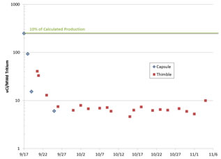
Fig. 5. Integrated tritium collected from the capsule and ICSA thimble exhaust gas. The final three points are taken during and after reactor shutdown but are adjusted for the equivalent time at 5.5 MW for direct comparison with the other data points.
model. 10% of this production rate is indicated by the line in Figure 5, aligning with the first measurement of tritium release from the capsule.
Although both capsule and ICSA thimble tritium levels decreased rapidly over the first week of irradiation, the thimble gas tritium release rates were consistently higher, indicating that the tritium diffused easily through the nickel capsule wall. The outside wall of the nickel is calculated to be about 50°C colder than the thermocouple, or ~650°C. At these temperatures metals are highly permeable to hydrogen, so such an effect is not unexpected compared to the smaller surface area available for axial diffusion of tritium from the salt chambers into the capsule cover gas stream.9
Future post-irradiation examination of the capsule and the material coupons will attempt to assess the total activity of tritium contained in the flibe and various materials and obtain a tritium balance for the experiment. Experience from the MSRE indicates that tritium, especially TF, will be preferentially adsorbed onto graphite.5 The large amount of graphite in the MSRE therefore substantially reduced the amount of tritium released from the system. Tritium may also have been held up in the experiment gas sampling system due to adsorption on the tubing. This can be countered in future experiments by mixing hydrogen into the helium cover gas mixture, but this was not done in this initial irradiation test for simplicity, and to prevent altering the redox potential of the salt.
Investigation of the condition of the capsule gas space and gas lines will also potentially yield information concerning the cause of the gas line obstructions. Finally, the flibe and material coupons will be used to assess corrosion, transport of corrosion products, and other material interactions with the liquid flibe environment under irradiation.
After cleaning and approximately one year of decay, the specimens’ activities were measured with an ion chamber and a germanium spectrometer. The SiC specimens had a surface dose rate of ~10 mR/hr; this was primarily β-activity and therefore likely due to 14C. The SS316 and Hastelloy specimens were approximately 100 mR/hr at 30 cm with contributions from 54Mn, 58Co, and 60Co. These isotopes are all expected activation products based on the composition of each specimen.
The final specimen weights are given in Table 3 along with the calculated mass loss. It should be noted that the surface area for the SiC/SiC fiber composite specimens used the bulk geometric area, not accounting for roughness or porosity, and therefore is an overestimation of the material loss.
For the metallic specimens there are two apparent trends; first, the specimens exposed in a binary environment without graphite had less mass loss than those in the ternary environment. Second, in each environment the SS316 corrosion rate was higher than that of the Hastelloy N. The SiC specimens in general had lower mass loss than the metals with the exception of the HNLS composite. Again, the increased apparent mass loss of the composites may be due to their open porosity increasing the available surface area for salt interaction.
Optical examination of the specimens via macrophotography and scanning profilometry produced results that agreed qualitatively with the weight change measurements. As shown in Figures 6 and 7, the surface of the specimens from the un-lined chambers had increased roughness, indicating some acceleration of corrosion due to the presence of the graphite surface. This is significant because in a salt-cooled reactor with solid fuel there will be significant exposed surface areas of both graphite and metal in the primary system.
TABLE III
Specimen Mass Change after Irradiation
Specimen |
Mass Change (mg/cm2) |
N1 (Hastelloy, lined) |
-0.23 |
N5 (Hastelloy, lined) |
-0.28 |
N2 (Hastelloy, unlined) |
-0.41 |
N6 (Hastelloy, unlined) |
-0.42 |
S1 (SS316, lined) |
-0.48 |
S5 (SS316, lined) |
-0.54 |
S2 (SS316, unlined) |
-2.09 |
S6 (SS316, unlined) |
-2.08 |
CVD SiC 1 |
-0.10 |
CVD SiC 2 |
-0.09 |
SA3 SiC/SiC |
-0.18 |
HNLS SiC/SiC |
-1.23 |
The TRISO particles were found to have cracking in their outer pyrolytic carbon layer (OPyC) that was not observed in surveys of the as-received particles, or in preliminary results from the autoclave tests at UW. Additional testing of repeated freeze-thaw cycles of TRISO particles in flibe found that previously-irradiated particles were much more susceptible to OPyC cracking than un-irradiated particles, however additional testing on larger batch sizes is required to definitively conclude that the irradiation sensitized the TRISOs to damage.


Fig. 6. Photographs of SS316 specimens after irradiation for lined (upper) and un-line (lower) chambers.

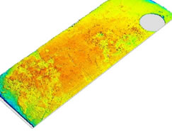
Fig. 7. Optical profilometry of the surface of irradiated SS316 specimens from lined (upper) and un-lined (lower) chambers.
A capsule containing fluorine-lithium-beryllium salt and a variety of material specimens was successfully irradiated in the core of the MIT Research Reactor for 1000 hours at 700°C. This irradiation marks the first demonstration of flibe irradiation capability at the MITR and the first irradiation experiment of the Fluoride Salt High-Temperature Reactor IRP.
Gas samples collected from the space above the flibe chambers and from around the sealed experiment capsule identified a steady release of tritium that is estimated to be only a few percent of the total tritium produced. Post-irradiation examinations will attempt to identify if the tritium balance can be accounted for by tritium absorption in the salt, the specimens, and the capsule’s structural materials.
These initial results provide evidence of the high potential mobility of tritium in an FHR system consisting primarily of liquid flibe, graphite, and high-nickel alloys at high temperature. At the same time, a large percentage of the tritium that was predicted to have been generated in the salt was not detected in the gas phase, mirroring experience from the MSRE and indicating a potential for tritium control through tritium capture in solid components.
The data collected from this irradiation is immediately applicable to plans for future flibe irradiation experiments. In particular, there is increased confidence in the modeling and thermal control of the capsule with liquid flibe. In contrast, the gas handling system will need to be redesigned to prevent clogging of the gas sampling lines. Additionally, minimization of gas volumes must be balanced with personnel dose considerations due to the high activity and mobility of flibe activation products at any temperature. Future work on understanding tritium partitioning and the differences between nickel alloys and SS316 will help inform the evolution of the FHR conceptual design.
Financial support for this work is provided by the U.S. Department of Energy through an Integrated Research Project grant. We would like to acknowledge the help of our colleagues at the MIT: Dr. Kaichao Sun, Dr. Charles Forsberg, John Stempien, Chris Haid, and the NRL staff; at UW: Dr. Mark Anderson, Dr. Guoping Cao, Brian Kelleher, and Guiqiu Zheng.
1 C. FORSBERG, et. al., “Fluoride-Salt-Cooled High-Temperature Reactors (FHRs) for Base-Load and Peak Electricity, Grid Stabilization, and Process Heat,” MIT-ANP-147, Massachusetts Institute of Technology (2013).
P.N. HAUBENREICH and J.R. ENGEL, “Experience with the Molten-Salt Reactor Experiment,” Nuclear Applications & Technology, 8, 118 (1970).
C. FORSBERG, “Fuel Geometry Options for Salt-Cooled Advanced High-Temperature Reactors,” Proceedings of ICAPP, Nice, France, May 13-18 (2007).
S.J. KIM, Y. OSTROVSKY, L.W. HU, G. KOHSE, "Thermal Analysis of High Temperature Irradiation Modules in In-Core Sample Assembly," Proceedings of the ANS Annual Meeting, San Diego, June 13-17 (2010).
R.E. THOMA, “Chemical Aspects of MSRE Operations,” ORNL-TM-4658, Oak Ridge National Laboratory (1971).
A.L. MATHEWS and C.F. BAES, “Oxide Chemistry and Thermodynamics of Molten Lithium Fluoride-Beryllium Fluoride by Equilibration with Gaseous Water-Hydrogen Fluoride Mixtures,” ORNL-TM-1129, Oak Ridge National Laboratory (1965).
C. FORSBERG, “2013 Annual Report: High-Temperature Salt-Cooled Reactor for Power and Process Heat,” NEUP 11-3272 Quarterly and Annual Report, October 20 (2013).
F.J. SMITH, L.M. FERRIS, and C.T. THOMPSON, “Liquid-Vapor Equilibria in LiF-BeF2 and LiF-BeF2-ThF4 Systems,” ORNL-4415 (1969).
http://www.euronuclear.org/e-news/e-news-48/SAFAR-1.htm
M. BELAL and A.J. D’Arcy
South African nuclear energy corporation
Church street west, Pelindaba, Pretoria 0001 - South Africa
The analysis of transients for the SAFARI-1 research reactor is done using the RELAP5/SCDAPSIM Mod3.4 system code, while the analysis of critical phenomena associate with the Critical Heat Flux (CHF) is done using available correlations within the code, such as the AECL look-up tables, or from literature such as Sudo and Mishima correlations discussed and applied in this work.
In this paper a proposal is made on the application of the Sudo scheme of correlations to predict CHF conditions, supplemented by the AECL look-up tables. The application was used to evaluate the low flow burnout phenomenon that may occur during the beyond design loss of flow accident.
In applying the scheme and during the course of the transient, various validity and applicability checks were made on flow patterns and heat transfer conditions. These conditions (e.g. hot channel exit equilibrium quality, flow pattern, rate of variation of the channel inlet flow rate, and range of the experimental data) were selected on the basis of RELAP5/SCDAPSIM modelling of the experimental rig used by Sudo, observations made by the experimentalists, and our understanding of the CHF mechanism associate with the burnout phenomenon.
In the analysis, the hot channel of the SAFARI-1 model was adapted to resemble the test rig used by Sudo. The model provides adequate simulation of the phenomenon and means for editing the required conditions mentioned above.
Moreover, the paper discusses the development and validation of the above-mentioned models to adequately apply the Sudo scheme, and presents comparisons with an unbounded (i.e. no condition check) application that would conclude a challenging condition to the fuel, as opposed to this work that concludes no physical burnout and the fuel remains intact during the course of the transient.
In this work a Beyond Design Basis Loss of Flow Accident (BDBA LOFA) for the SAFARI-1 research reactor was selected as a case study to discuss the application of the Critical Heat Flux (CHF) scheme proposed by Sudo and Kaminaga[1]. Moreover, this work makes an attempt to apply the scheme within the range of applicability, physical and experimental. The physical are that established on the basis of assumptions made in deriving the correlations and the experimental are the range of conditions or observations made during the experiment.
The selected case study is a BDBA scenario that contemplates the loss of offsite power to the primary pumps, accompanied by a loss of emergency power to the shutdown pump i.e. total loss of forced convection, additionally the failure of any of the control rods to insert and shutdown the reactor, and assuming operator actions that worsen the course of the transient.
Such BDBA accident scenarios are used as a concept to develop the emergency operating procedures and also for the emergency planning and preparedness. On one hand a best estimate plus uncertainties is conventionally used and on the other hand best estimate analysis can be used to reveal phenomenon that is taking place to adequately establish the counter design or procedural provisions or actions to reduce the consequences, slowdown or eliminate the phenomenon.
The main objectives of this work are to identify model adequacy and aspects of future development for best estimate simulation of scenarios that may challenge the integrity of the fuel.
In section 2 we discuss the scheme and in section 3 we perform a pre-assessment of the BDBA LOFA transient to establish the region of interest for the comparison of RELAP5/SCDAPSIM Mod3.4[2] against the experiment. In section 4 we summaries the results of this comparison and validation. This validation assisted in establishing the adequate approach in applying the scheme and revealed aspects that should be considered for future development. These aspects are discussed in this paper.
The CHF Scheme proposed by Sudo and shown in Figure 1 uses a dynamically set dimensionless mass flux that determines the correlation to be applied depending on the magnitude and flow direction. Figure 1 is divided into regions that depend on the dimensionless mass flux G*. The CHF in each region is respectively represented by equations 1 to 4 that is shown in the figure. When G*>G1* a difference in CHF is not observed between up-flow and down-flow and the CHF is well predicted by equation 4. When G2*<G*<G1* the CHF is predicted by equation 2 for down-flow and when G3*<G*<G1* the CHF is predicted by equation 1 with ∆T*SUB,o=0 for up-flow. When G*<G3* for both up-flow and down-flow the mass flux is very low or the flow condition is a counter-current flow, the CHF is predicted by equation 3. Moreover in this figure the blue line refers to up-flow directions and the red lines refers to down-flow direction, while the green line refers to both up-flow and down-flow directions. The red dotted line represent the summation of Equ.2 and Equ.3 that is originally developed by Mishima[3] and modified for applications by Sudo.
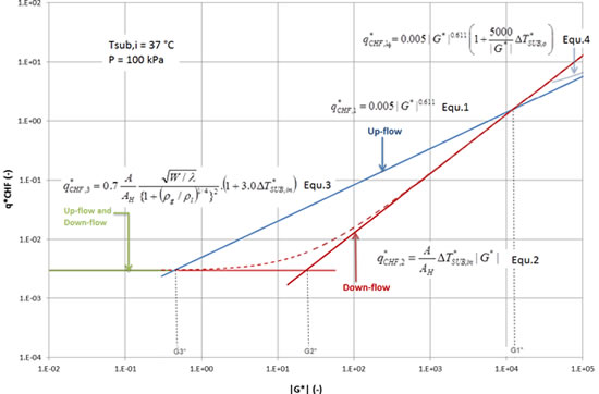
Figure 1: Sudo and Kaminaga CHF Scheme
where:
A |
:flow area of channel, m2 |
AH |
:heated area of channel, m2 |
q |
: heat flux, W/m2 |
q* |
: dimensionless heat flux = q" / hfg√ [λ ρg(ρl- ρg)g] |
W |
:width of channel, m |
G* |
:dimensionless mass flux = G / √ [λ ρg(ρl- ρg)g] |
λ |
:characteristic length |
∆TSUB,in |
:sub-cooling for channel inlet, ˚C |
∆T*SUB,in |
dimensionless sub-cooling for channel inlet = Cp ∆TSUB,in/hgf |
∆T*SUB,o |
:dimensionless sub-cooling for channel outlet |
ρg, ρl |
:vapour and liquid densities, kg/m3 |
Cp |
: specific heat capacity, J/kg.K |
hfg |
:latent heat of evaporation, J/kg |
|
|
In the above correlations; Equ.1 and Equ.4 are correlated to the experimental data[1], Equ.2 was derived assuming zero exit equilibrium quality[3], and Equ.3 is derived from the heat and mass balance[3] in the heated section and the flooding condition by Wallis[4]; Moreover, the parameters that dominated the resultant value of CHF is the mass flux G* followed by the channel inlet sub-cooling ∆T*SUB,in; while the values of channel configuration, namely, A, AH and W, are apparently fixed for the configuration under evaluation as shown in Table 1 of section 4 below. All other parameters are evaluated at the saturation conditions at the channel inlet.
The dimensionless mass fluxes Gi* (i=1..3) are the boundaries between the regions shown in Figure 1 and are calculated and defined as follows[1]:
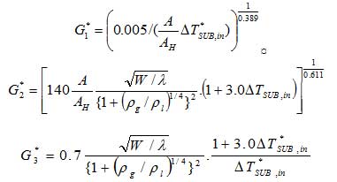
These dynamically calculated mass fluxes are compared with the actual mass flux in the hot plate channel, in terms of both magnitude and flow direction, to determine the applicable correlation (Equ. 1 to Equ. 4) to be used.
During the course of the DBA and BDBA LOFA the inlet sub-cooling varies between about 10°C and 80°C (80°C is the inlet sub-cooling during normal operation at 20 MW). Figure 2 is an extract of Figure 1 at the above inlet sub-cooling values where only the red and green lines are affected. The figure also superimposes the evolution of the hot channel dimensionless mass flux and heat flux during the course of the DBA and BDBA LOFA.
The main region of interest is highlighted when the mass flux G*(t) coincide with the heat flux q*(G*) that exceeds the predicted CHF (i.e. excess of CHF is mainly above the 10 °C inlet sub-cooling line which happen only in few instances during the transient as shown in Figure 3). This region of interest is used only for the comparison and validation of the RELAP5/SCDAPSIM model and to establish the adequate application of the scheme, knowing the procedure and steady conditions used during the experiment when compared with the steep variations in the actual transient. Nevertheless in safety analysis the margin to acceptance criteria should be considered which may reduce the lines shown in the figure by this criterion.
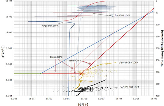
Figure 2: Extraction of CHF correlations of Figure 1 at 10°C and 80 °C of inlet sub-cooling, showing the DBA and BDBA LOFA actual dimensionless mass flux G*(t) and actual dimensionless heat flux q*(G*) and the region of interest.
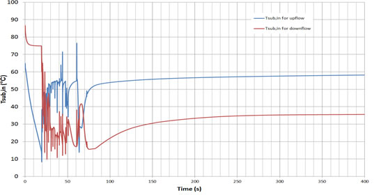
Figure 3: Inlet Sub-cooling during the BDBA LOFA for up-flow and down-flow
The CHF and the application of the Sudo scheme does not depend only on the G* value and configuration but also on a set of CHF operating parameters that are correlated empirically in the range of parameters tested, and on the mechanism of the CHF observed[5]. The main CHF operating parameters are the flow pattern, the channel exit conditions and the range of the experimental data.
In order to establish the CHF operating parameters mentioned above and to validate the application of the scheme, a comparison is made between the experiment conducted by Sudo and Kaminaga and the behaviour of RELAP5/SCDAPSIM code system. Figure 4 shows the SAFARI-1 core nodalization (left) and the RELAP model of the hot channel that resembles Sudo and Kaminaga experiment (right). Table 1 presents the model parameters used for the comparisons and also the key parameters of the experiment. The validation was focused on the range of mass and heat fluxes that represent the region of interest identified in section 3 above.
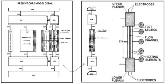
Figure 4: SAFARI-1 core nodalization (left) and RELAP model that resembles Sudo and Kaminaga experimental rig (right)
Table 1: Validation, Model and Operating Parameters
Model configration |
|||||
Flow channel width |
(mm) |
50 |
034 |
Inlet plenum |
|
Flow channel length |
(mm) |
750 |
026 |
Coolant channel |
|
Water gap width |
(mm) |
2.25 |
|||
028 |
Outlet plenum |
||||
Heated element width |
(mm) |
40 |
|||
Heated element length |
(mm) |
750 |
100, |
Inlet subcooling and pressure controls |
|
Operating parameters |
|
||||
Inlet subcooling |
(°C) |
37-39 |
|||
Flow direcition |
- |
Upflow, downflow |
|||
Flow rate |
(Kg/m2s) |
0 – 25,100 |
|||
Heat input |
(kW) |
Up to 0.1MW |
|||
Pressure |
kPa |
100 – 120 |
|||
The procedure for comparison at each G* value was as follow:
Obtain the predicted CHF at cold condition (i.e. P=1Watt) and at the inlet sub-cooling and system pressure shown in table 1,
Assign power to the hot plate in steps (about 60 s each) until a sharp increase in the surface clad temperature is obtained,
Assess the RELAP behaviour as the condition approach the CHF and at the CHF.
In RELAP model that resembles the experiment; twenty axial nodes were made to compare with the thermocouples used in the experiment. This is due to the fact that at certain conditions, and specifically for non-uniform heat flux distribution, the CHF and the sharp temperature increase can take place away from the hot-spot. Moreover, the models and correlations that govern the energy and momentum closure relations and special flow process models were varied to identify aspects that affect the comparison. Amongst these models the interphase friction, wall drag and the Counter Current Flow Limitation (CCFL) model of Wallis affect the comparison within ±10%. The dominant closure relation that derives the comparison is the wall-to-fluid heat transfer (i.e. the transition between heat transfer mechanisms and the application of the corresponding heat transfer correlation).
Figure 4 is an extract of Figures 1 and 2 showing results of the comparisons. The initial comparison (red triangles) were performed using RELAP model without special adjustments. Figure 5 shows a case during one comparison run. In this case the CHF predicted by AECL look-up table[6] and by Sudo scheme is shown. According to Sudo scheme the transition to transition or film boiling should take place at 650 s (see black arrow in Figure 5) when the actual heat flux exceeds Sudo predicted CHF, while the AECL CHF, that is implemented in RELAP5/SCDAPSIM, is orders of magnitude higher.
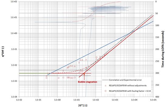
Figure 4: Comparison of Sudo and Kaminaga experiment and RELAP5/SCDAPSIM Mod 3.4 code.
As mentioned above that the dominante model that derive the comparison is the heat transfer logic while others provide ±10% variation, the adjuestment was done by selecting a foulding factor of 0.14 that reduces the heat transfer coefficients and the CHF solution. This adjustment, even if not adequate, was reasonable to study the impact of the transition logic in the comparison. The results are presented in Figure 4 (red rectangulars) which show the same trend as in the Sudo scheme. A slightly higher fouling factor can bring the comparison within the experimental error however it was found unnessary at this stage.
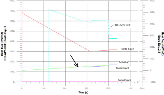
Figure 5: A sample of a comparison case showing the flow transition logic from nucleat boiling to transition or film boiling that depend on the CHF correlation implemented in the logic
The adjusted results were used to establish the conditions used to applying the Scheme and during the course of the transient. 0 shows the actual operating parameters stated by Sudo for equation 1 and 4[1], and by Mishima for equations 2 and 3[3], and the assumed operating parameters derived from the model validation and used in this analysis.
Table 2: Actual and conservatively assumed CHF operating parameters
Operating parameter |
Actual |
Assumed |
Xe,o(-) |
~<0 |
≥-0.02(1) |
Flow pattern (-) |
≥ANM |
≥SLG(2) |
Flow rate differential (kg/m2.s /s) |
~0 |
≤2.5e-03(3) |
Mass flux (kg/m2.s) |
-600 to +480 |
-600 to +480(4) |
Heat flux (MW/m2) |
Up to 1.3 |
Up to 1.3(6) |
This criterion is applied to equation 2 since it was derived from the condition Xe=0 (the negative qualities refer to sub-cooled conditions). The '~<0' was recommended due to the presence of unheated side walls. The conservatively assumed equilibrium quality corresponds to about 10-15 °C exit sub-cooling.
This criterion is applied to equation 3 and is based on the flow patter associated with the high quality flow burnout mechanism [1,3,5].
This criterion is applied to equations 2 and 3 as noted by Mishima[3]: “The results are obtained for steady inlet-flow condition and may be valid also for a slow transient”. The assumed value is the maximum variation during the flow reversal as derived from DBA LOFA. This criterion was also selected to study the influence of the timely behaviour required for the CHF condition to establish.
The range of the experimental data for equations 1. Outside this range the AECL based DNBR is used.
The range of the experimental data for equations 2 and 3. Outside this range the AECL based DNBR is used.
The range of heat fluxes for equations 2 and 3. Outside this range the AECL based DNBR is used.
Figure 6 shows the Burnout Ratio (BOR) and the inline application of Sudo scheme (via RELAP control variables) when conditions of Table 2 is not applied while Figure 7 shows the BOR when conditions of Table 2 is applied. From Figure 7 it could be argued that the adequate application of Sudo Scheme within the range and conditions of the experiment shows sufficient margin to burnout and the fuel stay intact during the course of this transient.
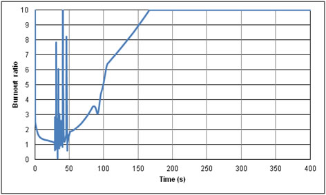
Figure 6: Burnout Ratio during the course of BDBA LOFA with unbounded application of Sudo Scheme
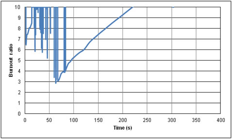
Figure 7:Burnout Ratio during the course of BDBA LOFA with a bounded application of Sudo Scheme
A detailed validation was performed of RELAP/SCDAPSIM Mod 3.4 against Sudo and Kaminaga experiment for the prediction of the CHF condition in a rectangular flow channel. This validation has identified the main drive of the comparison and the adequate application of the Scheme. The comparison was driven by the criteria used for the transition between heat transfer mechanisms to up to a factor of 5 while various models governing the two phase flow momentum and energy transfer vary the comparison with ±10%.
An adjustment was made to study the impact of the criteria used for the transition between heat transfer mechanisms which resulted in a better agreement with the experiment. The adjusted comparisons are used to establish the conditions of applicability of the Scheme.
The application of the Scheme, within the region of applicability, and during the course of beyond design basis loss of flow accident, showed a sufficient margin to burnout as opposed to deteriorating behaviour if the Scheme was applied outside its region of applicability.
[1] M KAMINAGA, K YAMAMOTO and Y. SUDO, "Improvement of Critical Heat Flux Correlation for Research Reactors Using Plate-Type Fuel", Journal of Nuclear Science and Technology, Vol.35, No.12, p. 943-951, December 1998
[2] RELAP5/MOD3.3Beta Code Manual, "Models and Correlations", VOLUME IV, section 4.2.3.5, page 135.
[3] MISHIMA, K., "Boiling burnout at low flow rate and low pressure conditions, Dissertation Thesis", Kyoto Univ., (1984).
[4] Wallis, G.B.:”One-dimensional Tow-phase Flow”, (1969). McGraw Hill.
[5] L.S.TONG, Y. S. Tang, "Boiling Heat Transfer and Two-Phase Flow", 2nd Edition, para.5.2.3, 1997.
[6] D. C. Groeneveld, S. C. Cheng, and T. Doan, "1986 AECL-UO Critical Heat Flux Lookup Table", Heat Transfer Engineering, 7, 1-2, 1986, pp. 46-62.
http://www.euronuclear.org/e-news/e-news-48/strategic-plans.htm
D. RIDIKAS
Department of Nuclear Sciences and Applications
International Atomic Energy Agency, Vienna International Centre, PO Box 100
1400 Vienna, Austria
E-mail: d.ridikas@iaea.org
Strategic plans are indispensable documents for research reactors (RRs) to ensure their efficient, optimized and well managed utilization. A strategic plan provides a framework for increasing utilization, while helping to create a positive safety culture, a motivated staff, a clear understanding of real costs and a balanced budget. A strategic plan should be seen as an essential tool for a responsible manager of any RR, from the smallest critical facility to the largest reactor. In fact, not only is it a document that can provide justification for the operational funding required for the facility, but it is also a powerful means of management control for all activities relating to the facility. A well prepared strategic plan will also provide on-going benefits to the facility management. However, due to its evolutionary nature, a strategic plan is a dynamic process, and therefore the plan will require monitoring and regular update to be truly successful.
In conjunction with this year’s planned revision of IAEA TECDOC-1212 on “Strategic Planning for RRs” (2001), and in order to reflect the current status and trends in RR utilization and management, a group of international experts has reviewed 37 strategic plans submitted by RR managers in 2013-2014. The resulting suggestions and recommendations were communicated to the originators for their consideration. Each strategic plan document was reviewed against the requirements of TECDOC-1212. Results were tabulated for each document individually and recommendations for improvement were communicated to the originators. The detailed review also indicated a scoring range from well-prepared strategic plans that required only a limited amount of attention and others which were notably insufficient in their preparation.
As a follow up to the review, two interregional workshops were organized in July 2013 and October 2014. They gave for the a great number of participating RR facility managers from close to 30 Member States the chance to share experiences, lessons learned and good practices in developing and implementing strategic plans at their facilities. The lively meetings, packed with experts’ lectures, country presentations and round table discussions, resulted in tangible suggestions and recommendations regarding how strategic plans should be prepared, revised and implemented. The concrete examples and case studies also provided additional input to how the TECDOC-1212, presently under revision, needs to be improved.
This paper will present in detail the results and lessons learned from the IAEA efforts to help the RR facilities developing strategic plans for effective utilization, provide review and advise services, organize national and regional stakeholder/user workshops, prepare further guidance and recommendations, document and publish guidance documents and other supporting materials.
The IAEA is convinced of the need for Research Reactors (RRs) to have strategic plans (SPs) for their utilization and has regularly issued a series of publications to encourage facility managers, operators and stakeholders in this regard. The first publication of “Strategic Planning for Research Reactors” was released as TECDOC-1212 in 2001 [1]. In the meantime, planning the utilization and administration of RRs has changed according to how new technologies, business strategies and organizational structures have developed.
The IAEA has also sponsored several meetings and workshops to facilitate the exchange of expert advice and local circumstances in order to improve the concept of research reactor strategic plans and their implementation. The outcomes of these meetings identified the need to revise the original TECDOC-1212 and to publish a new version that will provide an improved approach to assist both existing and new research reactor operating organizations. Such an approach would enable reactor management to determine more accurately the state of existing reactors or the intended operation of new facilities. At the same time, management could identify the capabilities of their research reactors and match these to stakeholders’ needs and establish the feasibility of supplying such needs. Management could then also establish a long term vision that would not only accomplish optimized utilization of the research reactor but would also promote the sustainability of the reactor and its ancillary facilities.
The review of the original TECDOC-1212 was also strongly recommended by the Technical Working Group on Research Reactors (TWGRR). Although the original TECDOC-1212 only focused on enhancing the utilization of existing RRs, this updated version now also provides guidance on how to develop a strategic plan for a new RR and will be of particular interest for organizations which are preparing a feasibility study to establish such a new facility. This revised publication, therefore, now complements the recently published RR Milestones document [2] and contributes to the important set of technical documents and guidelines recommended for new RR facilities. In addition, the concepts of the recently issued document on RR applications and utilization [3] are incorporated in this revision. The latter report brings together many of the current uses of RR and enables a reactor owner or operator to evaluate which applications might be possible with a particular research reactor facility. An analysis of a research reactor’s capabilities, both existing and potential, is an early phase in the strategic planning process.
This paper presents some major results and lessons learned from the IAEA efforts to help the RR facilities developing strategic plans for effective utilization, provide review and advise services, organize national and regional stakeholder/user workshops, prepare further guidance and recommendations, document and publish guidance documents and other supporting materials.
Assistance in preparation and review of SP documents is available as an IAEA service provided to the RR facilities. Indeed, SPs for RRs are key documents to ensure their efficient, optimized and well managed utilization - this applies to both existing and newcomer RRs. Newcomers benefit from a strategic plan by the justification of the project and by clarified definition of the specification of the RR and its ancillary facilities in order to optimize its future utilization. On the other hand, existing RR could benefit by re-evaluation of stakeholder needs in order to both continue operation and to optimally increase its utilization.
In conjunction with this year’s planned revision of TECDOC 1212 and in order to reflect the current status and trends in RR utilization and management, a group of international experts has reviewed 37 strategic plans submitted by RR managers around the world. The resulting suggestions and recommendations were communicated to the originators for their consideration. Each strategic plan document was reviewed against the requirements of TECDOC 1212. Results were tabulated for each document individually and recommendations for improvement were communicated to the originators. The detailed review also indicated a scoring range from well-prepared strategic plans that required only a limited amount of attention and others which were notably insufficient in their preparation.
In practice, the review of each individual SP document was completed according to a sufficiency scale (0 to 10) of section content according to the IAEA TECDOC-1212 proposals with the results tabulated for each SP. The outcome of this allocated review also indicated a range from “well-prepared SPs that required some attention with overall average, say, above 5” to some SPs which were “totally insufficient in their preparation with overall average, say, below 5”.
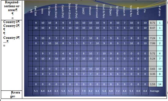
A selective ranking system based purely on average of un-weighted scores is given in Table 1 for comparison of the levels of SP sections-areas completed by the various facilities. The numbers are the granted points (from 0 to 10). Table 1 also includes specific country average for all required sections-areas (grey column), number of zeros for not included chapters-areas (bright-blue column) and section-area averaged score by all considered countries (last line).
Table 1: The levels of SP sections-areas completed by the various facilities
The involved experts recommended that the IAEA provide suitable feedback to each individual facility regarding the level of the SP preparation to still receive attention before the forthcoming workshop and then to address any outstanding shortcomings at the workshop and assist the applicable RR managers to complete their SPs to the required levels of sufficiency.
From Fig. 1 one can clearly observe that “Marketing”, “Finances”, “Action plans” and “Potential stakeholder needs” are the areas where the most attention is required by all.

Figure 1: Un-weighted performance of SP sections-areas, averaged over all RR facilities which submitted their SP for review.
Other observations by the experts were:
Most reports were submitted following the IAEA template – but
A few countries provided strategic plans in a different layout to that requested;
The general recommendation remains that these countries adapt their information to the IAEA TECDOC-1212 and provided format.
Most countries completed several of the seventeen sections, but not all countries provided all information requested;
Several countries referred to Annexes to their report but these were not received by the IAEA (and subsequently not made available to the reviewing experts);
Although several SPs had been dated as prepared in 2012 or later, many of the others were outdated, some very much so and had obviously not received the necessary managerial controls to ensure implementation;
Although several of the SPs reviewed applied the IAEA template there were very few that satisfactorily addressed all the review requirements of the performance indicators;
The current status of the facility was generally well described in the SPs, as well as the analysis of Strengths, Weaknesses, Opportunities and Threats (SWOT) of the facility;
Potential capabilities, strengths and opportunities on one hand and potential stakeholder needs are not always clearly correlated to one another;
Quantitative information on existing capabilities and existing stakeholder needs is often absent;
Operating schedules are missing, as are characteristics of facilities (e.g. neutron fluxes, maximum source strengths that can be handled), presence of auxiliary facilities such as hot cells or radioisotope processing plants;
It is difficult to draw conclusions on existing stakeholders’ needs if no information is given on, e.g. how often irradiations have to be provided, how many students are trained, how many samples are irradiated for NAA, etc.
The principal objectives – and derived specific objectives - mostly are based on the strengths and opportunities. However, many facilities report concerns in their SPs how the existing experience can be fostered, or expanded, but such weaknesses or even threats are considered only in a few cases as a principal objective for actions;
Both the specific objectives and derived action plans often contain sufficient detail, but the ones drafted using the Template’s tables demonstrate that they were drafted with attention to realization;
It is at least remarkable that only one facility explained in detail their outreach and marketing strategy and actions. This component was not specifically addressed as a mandatory item in the IAEA Template;
It is regrettable that facilities did not take the initiative of adding marketing strategy to their SPs. This, together with the fact that almost all facilities literally copied the IAEA template text for the executive management statement, i.e. without any facility-specific notes, may raise the question whether the SPs have been reviewed at the highest executive level.
As a follow up to the review process of the received SPs, two interregional workshops were organized in July 2013 and October 2014. Altogether, they gave for the a great number of participating RR facility managers from close to 30 Member States the chance to share experiences, lessons learned and good practices in developing and implementing strategic plans at their facilities (Fig. 2). The concrete examples and case studies also provided additional input to how the TECDOC-1212, presently under revision, needs to be improved.

Figure 2: Photo of participants and experts attending the IAEA Training Workshop on
“Development of Research Reactor User Communities and Industrial Partnerships”
IAEA Headquarters, Vienna, Austria, 13–17 October 2014.
The workshops also allowed facilitating the exchange of experts’ advice and local circumstances in order to improve the concept of RR strategic plans and their implementation. Such an approach enables reactor management to determine more accurately the state of existing RRs or the intended operation of new facilities. At the same time, management could identify the capabilities of their RRs and match these to stakeholders’ needs and establish the feasibility of supplying such needs. Management could then also establish a long term vision that would not only accomplish optimized utilization of the RR but would also promote the sustainability of the reactor and its ancillary facilities.
The following is a summary of the issues raised during the feedback session from the workshop participants regarding lessons learned during the expert and participant presentations and discussions.
The topics effectively covered SPs over the full range of RRs:
From “Small” to “Big”, and of various statuses from
Planned, Under construction, Operational (both well-utilised and under-utilised), Shutdown, to Being Decommissioned
There was in most cases a need for a national strategy and vision to enable the RR SP to be effectively applied
Most (all) RRs were dependent on Government funding
Assistance is readily available to help RR management - but managers need to be proactive
The choices among E&T / R&D / and Irradiation Services (IS) and Isotope Production (IP) are not always that simple
The preferred government strategy is rather E&T than R&D
There is often insufficient funding to carry on these activities
IS and IP are generally considered for income generation
The RR remains as a service provider for the above and is not the service/product originator
Common problems experienced across the RR SP profiles presented:
Funding
Loss of Personnel and expertise – Retirement, Relocation to industry
Ageing of staff and systems
Ability to find stakeholders/users and increase utilisation
Extended shutdown situation.
The workshop participants together with the experts also formulated a number of follow up recommendations to the teams involved in drafting facility SPs, namely they should:
Revise their SPs according to the expert review comments and the lessons learned during the workshop;
Follow-up the draft SPs by implementation, progress monitoring and evaluation, and review by facility’s own committee;
Share the lessons learned with relevant staff, top down and bottom-up;
Quantify capabilities, existing and future stakeholder’s needs; the latter in close communication with those stakeholders. If applicable, make an inventory of radionuclides and sources (and their strengths) imported and in use in the country;
Establish and quantify the performance indicators for monitoring progress and provide baseline values for the status in the reference year;
If applicable, initiate awareness building on RR utilization at universities and the public. If applicable, publish in the social media success stories of social-economical relevance;
Consider professional help in marketing, advertisement and sales;
Consider finding stakeholders also outside the country.
As one of the key outcomes of the SP review meetings/workshops, it was identified that there is a need to revise the original TECDOC-1212 and to publish a new version that will provide an improved approach to assist both existing and new RR operating organizations. The review of the original TECDOC-1212 was also strongly recommended by the Technical Working Group on Research Reactors (TWGRR). The Agency, in addition to the above mentioned follow up workshops, has organized a dedicated consultancy meeting (in May 2014 in Vienna), where a group of international experts have proposed and provided inputs to the following new structure of the future IAEA publication:
Part 1 – Guidelines: The purpose of this part is to put the formulation of a strategic plan into perspective, to provide a rationale for the development of a strategic plan and to give an overview of the process.
Part 2 – Preparation of a Strategic Plan: The second part of the document is a more detailed guide. It gives a suggested format for the plan and describes the considerations and content of each section. Selected question sets are used which aim at assisting the facility management in tailoring the plan to meet its needs.
Part 3 – Guidance on Specific Topics: The third part contains guidance on how to evaluate the financial implications to operate the facility, increase stakeholder awareness of the existence of the facility and how to attract stakeholder utilization. As mentioned above, a change in management and personnel mind-set is sometimes necessary - this is also described in this part of the document.
In addition, several Annexes have been added to this revised version of the document and include examples to clarify the methodologies discussed in the document and to thereby assist the preparers of the strategic plan:
Annex 1: Some strategic considerations that could be taken into account for the strategic plan’s preparation;
Annex 2: A template as an example of a typical strategic plan’s layout;
Annex 3: Clarification of the application of Strength-Weakness-Opportunity-Threat (SWOT) analysis and the relevant Probabilistic Risk Assessment (PRA) evaluation;
Annex 4: A typical questionnaire as an example of surveys required to determine capabilities and competencies required for a new nuclear center;
Annex 5: An example of evaluation methodologies for Key Performance Indicators (KPIs) required for a research reactor’s utilization;
Annex 6: Clarification of the concept of Eliminate-Reduce-Create-Raise (ERCR) analysis for achievement of an objective with a typical example; and
Annex 7: A completed (but filtered) strategic plan from an operational research reactor.
The schematic structure outlined below in Figure 3 is an illustration of the revised approach that should be considered when regarding the development of a strategic plan and its intended outcome. The outcome (roof) of a successfully implemented SP must result in optimized Utilization and Sustainability of the RR during its lifetime. This can only be achieved if the support system (pillars) of the applicable Stakeholders are sufficiently well developed to ensure implementation – e.g. by utilization of irradiation services, existence of R&D projects, and need for Education and Training (E&T) activities. A sound basis (foundation) for the structure is built according to the Stakeholder Engagement (through their needs and interests) which ensures that the resources are made available. These resources are normally the facility itself, funds required and the staff operating and supporting the on-going activities.
Finally, it must be emphasized that the methodology for the preparation of a strategic plan as identified in this revised document is purely a guideline and is not mandatory – unless it is a specific requisite by the IAEA when evaluating requests for technical/financial assistance. The IAEA does not expect general publication of plans or public disclosure of the information contained therein. The IAEA, however, recommends that it will prioritize support requests for new ancillary facilities or equipment for RR utilization if they are accompanied by a strategic plan clearly demonstrating that the items requested are necessary to achieve the objectives of the plan.
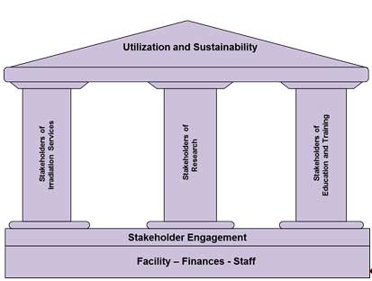
Figure 3: Modular approach for the strategic plan of a research rector.
The IAEA is convinced that the long-term sustainability of many RRs around the world depends upon the development and implementation of an effective and achievable SP for their utilization. It is hoped that the revised guidelines on how to prepare, efficiently monitor and successfully implement the SPs for RR facilities together with the offered IAEA services in preparation and review of SP documents will prove to be a key element to enhance RR utilization and ensure long term sustainability of the products and services these facilities can provide.
[1] INTERNATIONAL ATOMIC ENERGY AGENCY, Strategic Planning for Research Reactors — Guidance for Reactor Managers, IAEA TECDOC Series No. 1212, IAEA, Vienna (2001); presently under review with the new publication expected in 2015.
[2] INTERNATIONAL ATOMIC ENERGY AGENCY, Specific considerations and milestones for a Research Reactor project, IAEA Nuclear Energy Series No. NP-T-5.1, IAEA, Vienna, (2012).
[3] INTERNATIONAL ATOMIC ENERGY AGENCY, Applications of Research Reactors, IAEA Nuclear Energy Series, NP-T-5.3, IAEA, Vienna (2014).
http://www.euronuclear.org/e-news/e-news-48/PIME2015.htm


From 1 – 4 March 2015, the Slovakian capital city of Bratislava played host to PIME 2015, the ENS flagship conference for nuclear communicators. This annual event has been going on for well over a quarter of a century and has established itself as the benchmark conference for the nuclear industry’s communications professionals. Around 100 communicators from across the world, including China, Japan, South Africa, Canada, the US and Russia, gathered in Bratislava to discuss the burning communications issues of the day, to share experiences - successes and failures, and to identify new solutions to the many challenges that communicators face in today’s fast-changing and information-hungry world. For the tightly-knit international community of nuclear communicators PIME also provides a golden opportunity to meet and network with fellow professionals and to reconnect with friends and colleagues who share the same objectives.
PIME 2015 kicked off with a welcome address from Michele Bologna, Director of External Relations at the conference hosts, Slovenske Elektrarne, which is an ENEL Group company. During the traditional host country presentation Miroslav Obert, State Secretary for Economy of the Slovak government then gave an overview of the nuclear scene in Slovakia, stressing how for his country nuclear energy is so vital for a well-functioning energy market and for achieving the low-carbon goals - not just of Slovakia, but also of the EU. He also outlined the many communications activities that the government has launched to engage and inform stakeholders in Slovakia.
Next up on stage was Nicola Cotugno, CEO of Slovenske Elektrarne. He gave a detailed account of his company’s activities in Europe, Latin America, Africa, etc. Slovakia has four reactors currently in operation at Bohunice NPP and Mochovce NPP. It is also flying the new build flag with units 3 and 4 planned at Mochovce by 2016 and 2017 respectively. Slovakia also has some thermal, hydro and solar plants, but nuclear is the largest energy producer in the country, providing 52% of its electricity. Mr. Cotugno said that Slovenske Elektrarne are proud of the low-carbon footprint left by the Slovakian nuclear sector and stressed how the company is continually seeking to decrease its impact on the country’s environment with, among other things, activities aimed at reducing its liquid waste production.
Jean-Pol Poncelet, Secretary General of ENS, welcomed ‘Pimers’ on behalf of ENS and thanked both the first speakers for their interventions. He first presented the results of the Nuclear Industry Summit (NIS2014) that took place in Amsterdam in March 2014, before talking about the recently-launched Nuclear for Climate initiative that brings together nuclear societies and associations from across the world that are keen to promote the climate change credentials of nuclear energy ahead of the COP21 climate talks scheduled for Paris (December 2015). The initiative was partly inspired by the successful social media campaign that underpinned NIS2014.
After the opening speeches representatives of the five communications campaigns shortlisted for the PIME 2015 Award for Communications Excellence came up on stage to ‘sell’ their respective campaigns to PImers. The campaigns were also on permanent display during the coffee and lunch breaks and, ultimately, delegates were able to discuss the campaigns with their creators and carry out a peer review of each one, before voting for their choice as the winner of the award.
The first plenary session was entitled: Successful communications – getting your messages and tools right. It focused primarily on ways of increasing the impact and outreach of your organisation by articulating messages that are tailor-made to suit to specific target audiences. This was also the central theme of the presentation given by a Dutch consultant, Anke Laarhuis, from Buro Blink, who stressed that communicators must strive to better understand the motivations and expectations of their specific audiences if they want to turn what is often a sterile monologue into a positive dialogue. Buro Blink has developed a new strategy based on five storylines that target different audiences. But first it is vital to determine what the ‘brand personality’ and characteristics are for every specific audience. For example, one of the storylines was targeted at 8-16 year olds and was created by educational and cultural partners.
Miel van Opstal, from Wavelab (Belgium) then turned Pimers’ attentions to how communicating visual content via the boiling cauldron of social media can pay dividends. He stated that research shows that 90% of the information transmitted to our brain is visual. He also emphasised how Twitter is betting big on its ‘native video player,’ and on how Facebook and Youtube are competing head-on through the power of visual communications.
The two aforementioned plenary presentations then featured large during the afternoon’s workshops, where they were further developed with the hands-on participation of delegates. There were three workshops on offer, which were entitled: Towards receiver-oriented communications, Communicating with videos and Using the opportunity of an international event for communications – looking at the examples of the Nuclear Industry Summit 2014 and COP 21. In the last-mentioned workshop (which the author of this report attended) Bonnie Forster (Urenco), Eric van Leeuw (COVRA) and Isabelle Jouete (SFEN) analysed how important global events like NIS 2014 and COP21 provide an invaluable opportunity to draw attention to the benefits of nuclear energy to a large international audience. Isabelle presented in detail the Nuclear for Climate campaign that Jean-Pol Poncelet had flagged in his opening speech. Then delegates were divided into small teams and set about defining objectives and actions and to deliver results. The results of all three workshops were then presented and discussed in plenary.
In the afternoon plenary session the focus switched to the subject of: Building a case for nuclear – how political and economic developments influence communications strategies. Political, social and economic climates are changing all the time. This influences communications strategies that continually need to adapt and refocus in order to keep pace with events. Communicators must adapt to change or risk not connecting with their audiences.
Takuya Hattori, from the Japan Atomic Industry Forum; Marielle Rogie, from the Belgian Nuclear Forum; Valentina Dinu, from Nuclearelectrica (Romania) and Li Jianwei from State Nuclear Power Technology Corporation (China) then gave an overview of the communications challenges associated with economic and political change in their respective countries, countries that have very different cultural and social profiles. Among the tools they outlined as useful in helping to readjust the communications strategy cope with change were synchronising the strategy with the individual market context, and carrying out ‘image indicator’ analysis.
After a long day discussing key issues, working in break-out sessions and learning from the experiences of others Pimers were able to relax and enjoy the amazing hospitality offered by the hosts, Slovenske Elektrarne, during the Gala Dinner that took place at the Old Market Hall in downtown Bratislava. In the impressive surroundings of what was once the largest covered market in the city delegates enjoyed a buffet lunch and were blown away by a stunning display of Slovakian folk music and dance by an electric band of musicians and dancers. It was a memorable end to a very busy day.
On Day 2 the PIME 2015 spotlight fell on the first plenary session of the day, entitled: Opinion polls.
The first speaker was Peter Thijssen, of M2P Media, Movement & Politics, University of Antwerp (Belgium), who asked the central question: Are opinion polls a research tool or a communications device? He explored the relationship between the media, opinion polls, politics and democracy and to what extent the media shape rather than reflect public opinion when covering the results of polls. He also explained when the public can experience the ‘bandwagon’ or ‘underdog’ effect that poll results create. Finally, he cast doubt on the use of poll sampling based on ‘loaded’ or biased demographics.
Isabelle Jouette of SFEN then described how her organisation participated in ‘citizen committees’ and used telephone and face-to-face interviews to collect opinion data during France’s national debate on energy transition. In this way, she said, SFEN was able to keep its finger on civil society’s pulse and engage with stakeholders. She outlined how respondents’ reactions to nuclear can be broadly characterised according to five main categories: ‘confidents,’ ‘resigned,’ ‘reasonable realists’, ‘anxious realists’ and ‘opponents.’
Delegates were able also to appreciate from these debates how long-term operation is not a real subject of discussion, and that the only genuine debate is ‘nuclear or no nuclear.’ Those lessons were incorporated into their overall communications strategy.
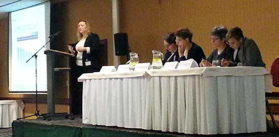
The final speaker was Sarah Crane of the UK’s Nuclear Industry Association (NIA). Her presentation looked at how opinion polls can be integrated into a broader communications strategy to emphasise key messages about new build, decommissioning and climate change. She stressed the importance of regional perspectives and motivations, of credible spokespersons and advocates, and of which methodology to adopt to make the most out of opinion polls. Following the presentations the three speakers were joined in a panel debate with the floor by Lenka Ferencakova, Editor-in-Chief of Energia.sk.
Attention then switched to three workshop topics from which Pimers were able to choose. The first one, Using opinion polls in a communications strategy, was chaired by Nathalie Guillaume of the CEA (France’s ‘Atomic and Alternative Energy Commission’). It focused on examples of the approaches used and methodologies adopted in different and how opinion polling is a mainstay of respective communications strategies in their countries, providing participants with a list of ‘do’s’ and ‘don’ts’. Among those who presented case studies and animated the debate were Christian Taillebois, of EDF, Katarzyna Wlodek-Makos, of PGE (Polish utility), Matthias Meersschaert, of the Belgian Nuclear Forum and Nathalie Guillaume herself.
The second workshop was entitled: The economics of nuclear. The debate was animated by Marco Streit of the Paul Scherrer Institute in Switzerland (a former President of ENS) and Lubomir Mitev, a correspondent at NucNet. Participants in this workshop analysed the important economic vectors relating to nuclear and explored the dynamics of nuclear economics in general. Among the issues discussed were the liberalisation of energy markets, grid interconnections and the controversial subject of subsidies.
The final workshop looked at the topic of: Debunking nuclear myths – the pre-conceived and ideology-driven misconceptions that wrongly drive public opinion and that are regularly targeted by nuclear communicators keen to expose the myths and reveal the truth. Eileen Radde, Co-chairwoman of the ENS Young Generation Nuclear ENSYGN), and Jeremy Gordon of the World Nuclear Association (WNA) examined how public opinion with regards to nuclear energy can be guided by scientific fact or by entrenched ideological positions. It is the job of nuclear communicators to present the facts in an interesting, understandable and engaging way so that they can debunk those myths and misconceptions; it’s all about setting the record straight and hammering home the message about the real benefits of nuclear energy.
The afternoon plenary session focused on a topic that has regularly featured at PIME conferences over the years, namely Learning from other industries. Two different industries, the medical and the space exploration sectors, provided fascinating insights into the particular challenges that each sector faces. Delegates were able to assess how the nuclear industry might learn something from their communications strategies, tools and methods, and potentially apply it to their own context.
The first speaker was Juliette van der Laan of the company Eurotransplant, in the Netherlands, an organisation that operates in the human organ transplantation sector. Juliette, who had previously worked for many years in the nuclear sector, highlighted the serious ethical and social questions that shape their communications strategy. It is, like nuclear, a topic that arouses great sensitivities and emotions, and is often perceived as being controversial. But, like nuclear, saving lives through providing organ transplants has a vital contribution to make to citizens’ quality of life. She particularly focused on the use of media, social media, public awareness campaigns and best communications practices. Unlike nuclear, however, Juliette emphasised how organ transplantation is ‘a very personal choice, ‘whereas nuclear is ‘just there.’
The final workshop, which was also the final session of the conference, was a visually inspiring and unforgettable presentation on the deep space exploration work carried out by the European Space Agency’s (ESA) for its renowned Rosetta mission. Mark McCauchrean, of ESA, introduced Pimers to the Rosetta mission, which consisted of landing the Philae probe on a comet in outer space - Comet 67P/Churymov-Gerasimenko. This was historical achievement - the first time in history such an incredible feat had been achieved. The extraordinary film footage of the mission and the other visual productions and communications tools created around the ground breaking Rosetta mission were very impressive and helped ESA to communicate in an inspirational way about what is a highly complex technological issue.
 |
After the previous presentation delegates were literally brought back to Earth with the Closing Session. Jean-Pol Poncelet announced the winner of the 2015 PIME Award for Communications Excellence: it was Slovenske Eletrarne for for their new state-of-the-art visitor centre, called Energoland. Robert Holy, Head of NPP Communications at Slovenske Elektrarne, went up on stage to collect the award accompanied by great applause. To win on home soil was particularly meaningful for Slovenske Elektrarne. Energoland features the very latest ‘edutainment’ tools, hands-on interactive exhibits, clearly explained displays and info-graphs and the very latest in 3-D audio-visual technology. The result is a highly interactive and evocative world presented in a unique atmosphere, where visitors can learn in a fun way (what it referred to as ‘A new dimension of knowledge’) about the central place that nuclear energy has always had in the history of the planet. It won a clear majority of Pimers’ votes. From a communications perspective it sets the bar very high. |
Jean-Pol Poncelet then delivered his closing speech, thanking the hosts and sponsors, congratulating the organisers of the conference and the many speakers and moderators who animated the agenda, and providing some personal observations and thoughts on the conference. Finally, he officially brought the PIME 2015 conference to a close with a traditional farewell drink.
The following day, delegates who had stayed on in Bratislava for the technical tours were given a choice of two venues to visit: the Mochovce NPP with its brand new Energoland Visitor Centre at the Mochovce NPP, which could now proudly proclaim itself as winner of the PIME 2015 Award for Communications Excellence, or the Bohunice V2 NPP. The author of this report visited Energoland, where Robert Holy and his team were the tour guides. It was easy to see why it had won the approval of so many communications specialists and won the 2015 PIME Award for Communications Excellence!
For further information regarding the conference visit the PIME 2015 website at: http://www.euronuclear.org/events/pime/pime2015/index.htm
Mark O’Donovan, Editor-in-Chief of ENS NEWS
http://www.euronuclear.org/e-news/e-news-48/ygn-report.htm

In 2015 it was Bucharest’s turn to host the annual European Research Reactor Conference (RRFM 2015), an event organised by the European Nuclear Society (ENS) in collaboration with the Romanian Nuclear Energy Association (AREN), the International Atomic Energy Agency (IAEA), and Électricité de France (EDF). From 19 to 23 April, RRFM 2015 brought together around 200 experts from more than 32 countries that shared their vision and experience on a variety of topics related to the world of research reactors, and presented more than 100 papers and 30 posters.
The agenda began with a Welcome Reception held on 19 April, and was then followed by 3 days of presentations and discussions, and ended with some technical tours. The topics debated in the parallel sessions varied from fuel development and quantification, to innovative methods in analysis and design of the research reactor, fuel fabrication & conversion, Moly99 production to safety and security concerns, back-end fuel cycle, decommissioning, and waste management perspectives. Other sessions were dedicated to new research reactor projects and common international topics.
The conference kicked-off with an opening session during which. Edgar Koonen, of SKG-CEN in Belgium & Chairman of the conference, gave a speech. Then Mihaela Stiopol, President of AREN, and Daniela Lulache, CEO of NuclearElectrica, gave key-note addresses. Daniela Lulache gave a brief overview of Romania’s nuclear programme and its perspective of expanding the programme with the addition of two more nuclear units at Cernavoda site. Ms. Stiopol explained what AREN is and outlined the activities they are doing to gain public acceptance of nuclear energy in Romania. The opening session ended with a speech from Maria Roth, Strategy Development Manager at the Institute for Nuclear Research, in Romania. She highlighted Romania’s nuclear research programme, emphasising the importance given to international cooperation in R&D. She also gave delegates a glimpse of how the Romanian research community is involved in the development of the Gen. IV EUROPEAN Lead Fast Reactor Demonstrator (ALFRED).
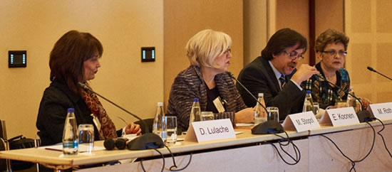
The program continued with parallel sessions where, among the many other interesting subjects, Ms. Lin-wen Hu presented a paper entitledthe “STATUS OF THE FLUORIDE SALT HIGH TEMPERATURE REACTOR MATERIALS IRRADIATION TESTS AT THE MIT RESEARCH REACTOR”. Her presentation was a definite highlight of Day 1. It emphasised the importance of following a path towards a commercially viable version of a fluoride-salt-cooled, high temperature reactor, and revealed the status of the first irradiation test done at the Massachusetts Institute of Technology Research Reactor, in the US.
During Day 2, Mr. Belal, from the South African Nuclear Energy Corporation, addressed a world-wide safety related subject. In his paper, “ASSESSMENT OF THE BURNOUT PHENOMENON IN THE SAFARI-1 RESEARCH REACTOR”, he proposed the use of the Sudo scheme of correlations for prediction of CHF conditions in research reactors and assessed the validity of the concept.
Day 3 was dedicated to the social programme, with delegates able to could enjoy the dinner laid on at the Diplomate Ballroom of the Athenee Palace Hilton, in Bucharest. The venue is famous for its great architecture and is situated close to the Romanian Athenaeum Concert Hall, a landmark in the Romanian capital city. The dinner was followed by a traditional folk dancing performance that introduced the distinguished guests into the cultural richness of Romania.
Traditional Romanian folk dancing
On Day 4, one eye-catching paper presented was entitled: “DEVELOPING STRATEGIC PLANS FOR EFFECTIVE UTILIZATION OF RESEARCH REACTORS.” It was delivered by Dr. Ridikas D. from IAEA, who emphasized the need fora strategic plan to ensure a ‘more efficient, optimized, and well-managed utilization’ of research facilities with respect to the IAEA TECDOC 1212. After the presentations and conference sessions RRFM 2015 ended with a closing session chaired by Edgar Koonen and the awarding of the Best Poster Prize.
The next day, delegates had a chance to visit the Cernavoda NPP and the TRIGA Research Reactor at ICN Pitesti. The Cernavoda site features 2 CANDU reactors, with 2 more currently under construction. At Pitesti the TRIGA research reactor and the CANDU nuclear fuel factory are located.
From my personal point of view, having attended RRFM for the first time, I would say that I am very thankful to ENS for providing me with an opportunity to participate as a ‘Young Generation Reporter.’ The conference offered a rich exchange of professional experience and helped make attendees more familiar with the impressive world of research reactors. The opportunity to meet and discuss with top experts from around the world, and ultimately to make new friends, was an enriching experience. I would like to encourage all Young Generation members to attend RRFM 2016, which will be held in Berlin, Germany.
Alin TATU,
Young Generation Reporter
http://www.euronuclear.org/e-news/e-news-48/TopFuel2015.htm

TopFuel 2015 will take place from 13 – 17 September 2015 in Zurich, Switzerland
TopFuel’s primary objective is to bring together leading specialists in the field from around the world to analyse advances in nuclear fuel management technology and to use the findings of the latest cutting-edge research to help manufacture the high performance nuclear fuels of today and tomorrow.
The TopFuel 2015 programme revolves around a combination of plenary presentations and technical tracks on:
Operation and experience
Transient Fuel Behaviour
Advances in designs, materials and manufacturing
Enhanced accident tolerance (ATF)
Modelling, analysis and methods
Used fuel storage, transportation and re-use/material recovery
The programme and more information is available on the TopFuel 2015 conference website: www.topfuel2015.org.
TopFuel 2015 Gold Sponsor
![]()
TopFuel 2015 Silver Sponsor
Organised in cooperation with:
and |
|||
|
|||
http://www.euronuclear.org/e-news/e-news-48/nuclar-institute.htm
Press Release Monday 16th March 2015

The Nuclear Institute (NI) has today announced that the Nuclear Delta™ has been officially trademarked, supporting its authority as a unique definition of attributes to identify nuclear professionalism across the industry.
Professionalism is vitally important to the nuclear sector in order to maintain the highest standards of safety and security within sensitive working environments and for the general public.
The Nuclear Delta™ is the definition of attributes that separates a nuclear professional from other professionals and is used in the membership process for all professional NI members. In simple terms, scientists, engineers, technologists, safety, security, and business specialists become nuclear professionals by becoming members of the Nuclear Institute and achieving the standards set out in the Nuclear Delta™.
The Nuclear Delta™ was established by the Nuclear Institute in 2010 and is unique in that it presents additional criteria to other professional institutes/institutions.
In particular, the Nuclear Delta™ specifically includes nuclear safety culture, nuclear security culture, nuclear safety and nuclear technology; in addition to the general technical, quality, health, safety and environment requirements as necessary for registration and membership of other professional institutes/institutions.
Clive Smith, Nuclear Institute Membership Committee Chair, said:
"The Nuclear Delta™ provides the benchmark for competences for those working in the nuclear industry. NI professional members are measured against the Nuclear Delta™ which, in conjunction with discipline specific skills, enables them to readily demonstrate their commitment to the high standards necessary within the nuclear sector along with their nuclear professionalism.”
Nuclear Institute President Tim Chittenden, commented:
"The Nuclear Delta™ summarises those key attributes of a nuclear professional which are the common denominator of members of the Nuclear Institute; it is important that all of our stakeholders recognise the commitment to nuclear professionalism made by our members so we have taken steps to protect the term from potential abuse by others who may not share our values."
Nuclear Institute CEO, John Warden, said:
"As the nuclear industry grows to meet the demands of nuclear new build sites, plant life extension work, and complex decommissioning projects, there is a pressing need for individuals and their employers to be able to demonstrate their ability to work safely and effectively in a nuclear environment. The Nuclear Delta uniquely captures this and allows those in the nuclear industry and those wishing to enter it a means of objectively demonstrating their nuclear professionalism."
http://www.euronuclear.org/e-news/e-news-48/nene2015.htm

The Nuclear Society of Slovenia cordially invites you to submit your abstracts for the 24th International Conference Nuclear Energy for New Europe. The conference will be held in the attractive maritime resort of Portorož, from 14 - 17 September 2015.
The conference is a traditional annual meeting for professionals from nuclear research and educational institutions, nuclear vendors, utilities and regulatory bodies. It attracts around 200 participants from more than 20 countries. The topics discussed range from reactor physics, thermal hydraulics, probabilistic safety assessment, severe accidents and nuclear fusion, to nuclear power plant operation, nuclear materials, waste management, new reactor designs, nuclear legislation, education and public information.
The abstract submission deadline has been extended until
May 30, 2015.
The conference website URL is www.nss.si/nene2015/.
For more information contact nene2015@ijs.si.
http://www.euronuclear.org/e-news/e-news-48/sne-news.htm

The Spanish Nuclear Society (SNE) organized one again its yearly winter meeting, Nuclear Power Plants in 2014. Experiences and Perspectives, in which Spanish nuclear industry representatives discussed issues relating to nuclear power plant operation in 2014 and addressed the future of the nuclear industry. The meeting was once again attended by university representatives, both teachers and students.
 |
 |
The Nuclear España Best Article Prize was awarded this year to the paper entitled: AEA International Missions to Japan on proposed decommissioning of the nuclear power plant Fukushima Daiichi TEPCO-and rehabilitation of areas affected by the nuclear accident, which was written by Juan Carlos Lentijo. The Commission also gave an Honorific Mention to the magazine edition called Maintenance.
 |
 |
A Special Mention was also given to the 30th Anniversary of Cofrentes N.P.P
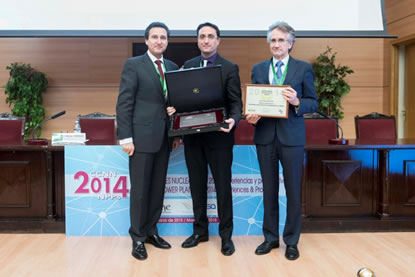
The SNE Ordinary General Assembly convened immediately after the meeting.
The 41th Annual Meeting will be held from 23 to 25 September of 2015, in the city of Coruña. It will be hosted by Gas Natural Fenosa. All the relevant information about the meeting is available at: www.reunionanualsne.es.
The Terminology Commission, whose mission is to define in Spanish - and with the highest degree of accuracy - the nuclear vocabulary that is used in the fields of science, technology and management, has updated 37 nuclear terms in its “glossary.” The glossary can be consulted on the SNE’s website at: www.sne.es. A total of 1,187 nuclear words are featured, alongside their French and English translations.
WiN Spain New Board and Celebration of WiN Spain 20th Anniversary
During the recent General Assembly, the WiN Spain Board was reconstituted and Matilde Pelegri was elected as its new President. During the first meeting of the new Board the Activity Plan for 2015 was approved. In addition to the continuity that it provides through the organisation of conferences aimed at informing society in general, it is worth mentioning the special interest that WiN Spain has to open up its organisation to other professional women from related associations, such as those representing companies working in radiological protection, medical physics and fusion.
In addition, WiN Spain will also celebrate its twentieth anniversary in 2015. Various activities are being prepared to commemorate this event. With the objective of analysing the evolution of WiN Spain, the relationship it enjoys with other organisations and the challenges it faces in the future, Nuclear España, the journal of SNE, published an interview in which the current President, Matilde Pelegri, was joined by the four previous WiN Spain Presidents: María Teresa López Carbonell (1995-2001), Carol Ahnert (2001-2006), Inés Gallego (2006-2011), and Maribel Gómez (2001-2014).
 |
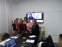 |
SPANISH NPP NEWS
The contribution of Spanish nuclear power plants in 2014 to electricity in Spain was equivalent to 21,9% of the country’s total consumption. Nuclear generation was in fact the top-ranking energy source in Spain, followed by wind, 20,4%; coal, 16,4%; hydraulic, 15,4%; cogeneration, 10,4%; gas combined cycle, 8,5% and the remaining renewables, 7%.
http://www.euronuclear.org/e-news/e-news-48/nuclar-institute2.htm
Nuclear Institute - Press Release
Tuesday 5th March 2015: FOR IMMEDIATE RELEASE
The agreement, which is supported by the Nuclear Institute (NI), the National Skills Academy Nuclear (NSAN), and the Institution of Chemical Engineers (IChemE), will facilitate closer alignment between the three organisations in a coordinated effort to encourage new entrants to the nuclear sector.
John Warden, CEO of the Nuclear Institute, said:
"Closing the skills and knowledge gap facing the industry is a crucial task. We need to secure a new generation of skilled nuclear professionals to meet the energy demands of a growing population. The Nuclear Institute has always been committed to promoting the highest standards of professionalism and we are very much looking forward to deepening our relationship with NSAN and IChemE to develop careers and show young people the exciting opportunities that are available to them."
The collaboration has been positively received by Mr. John Clarke, CEO of the Nuclear Decommissioning Authority, who said:
“The highest standards of nuclear professionalism are required to ensure a safe and secure nuclear future for the UK. I am delighted that NSAN, IChemE and the Nuclear Institute are formally collaborating to address this need.
Mr. Clarke went on to praise the interdisciplinary collaboration as a model for how future growth in the nuclear industry will be accomplished with safety and professionalism to the fore:
“In particular, the development of a joint membership offer between the Nuclear Institute and IChemE is an excellent development bringing together technical disciplines and nuclear sector specific requirements. I am confident that this will have a significant impact in terms of raising and recognising nuclear professionalism across the industry.”
The Nuclear Energy Skills Alliance’s Workforce Assessment Model reports that the total workforce in nuclear is expected to grow from 70,000 to 98,000 by 2021. Direct supply chain support for Operations, Decommissioning, Engineering, Construction, and Defence is forecast to require recruitment for 3,000 technical roles and 3,500 professional roles per year for current plans to be met. The Manufacturing workforce required is also expected to grow significantly to 8,500 from 4,000 reported in 2014.
However, despite this high demand for new recruits, a 2014 survey, completed by the Nuclear Industry Association (NIA), of more than 1,300 young people studying science, technology, engineering or maths subjects revealed that more than one third of respondents did not believe they could work in the nuclear industry. Moreover, one in seven questioned had not heard anything about career opportunities in the nuclear sector.
The new collaboration will address this knowledge gap head-on and promote the nuclear industry as an exciting career path.
The collaborative agreement was signed ahead of the nuclear skills summit meeting in London on April 29th. The partners’ first work programme will be published later this year.
http://www.euronuclear.org/e-news/e-news-48/nuclar-for-climate.htm
The ongoing global climate talks that are expected to culminate with an agreement at COP21 in Paris, in December 2015, prompted nuclear associations and societies from all over the world to launch an initiative called Nuclear4Climate. Avid readers of ENS NEWS will have seen the article about the campaign that featured in ENS NEWS N° 47. The goal of this campaign is to fuel the debate about how to fight climate change and highlight the essential contribution of nuclear energy to that fight. Nuclear4Climate brings together 60 trade associations and fora from around the world (including ENS, FORATOM, the French Nuclear Society (SFEN) and the American Nuclear Society – ANS to name but a few) that are keen to promote nuclear energy’s game-changing contribution to reducing CO2 emissions.
Most readers who are active in the nuclear community will already be well aware of the impressive climate change credentials of nuclear energy. At a time when the EU is more than ever determined to achieve its low-carbon economy goals, the role of nuclear - as a non-CO2 emitting energy source - in mitigating the effects of climate change is vital. However, not all readers may be quite so familiar with nuclear energy’s environmentally-friendly profile. By raising awareness of this fact the Nuclear4Climate campaign is spreading the word and bringing the debate about nuclear energy’s contribution to a large, environmentally-conscious and information hungry audience.
But what are the facts? Important studies have consistently demonstrated that nuclear energy must be part of the solution to meet increasing electricity demand while reducing greenhouse gases. For example, nuclear power provides 11% of global electricity production, 27% of Europe's electricity and 53% of its carbon-free electricity. According to the latest World Energy Outlook published by the IEA, it has already avoided the release of around 56 Gt of CO2 since 1971, which is equivalent to two years of emissions at current rates. By 2040, it is foreseen that the release of almost four years of CO2 emissions at current rates will have been avoided.
During the 2015 International Congress on Advances on Nuclear Power Plants (ICAPP), which recently took place in Nice, France, the Nuclear4Climate campaign grabbed the media and social media spotlight by organising the signing of a Joint Declaration by representatives of the main supporting organisations. This event, in which 40 nuclear societies representing more than 50,000 nuclear scientists took part, is part of a series of initiatives carried out by Nuclear4Climate under the aegis of its international campaign.
Among the other events that have already helped raise awareness are the presentation of the initiative by the Nuclear Engineers of Turkey (NMD) association during a session of the Istanbul Nuclear Power Plants Summit (INPPS) that took place in Istanbul on 20 March.
In Tokyo, on 13 April, the Japanese Atomic Industry Forum (JAIF) published a Nuclear4Climate Position Paper on their website (in Japanese), an initiative that truly reflects the international dimension of the campaign. In addition, ANS, the Australian Nuclear Association, the Belgian Nuclear Forum (BNF), JAIF, SFEN, the World Nuclear Association (WNA) and the Swedish Nuclear Society have created their own Nuclear4Cliamte websites.
Another initiative is called Take your picture! Since Nuclear4Climate is above a grass roots campaign, professionals working at nuclear installations were invited to take photos of their place of work. So far, over 200 people have supported of the campaign by photographing where they work and what they do. Among the photos are some taken in Paris, Washington DC, Pheonix, Istanbul, Beijing, Thailand, Malaysia, etc. To have a look at some of them m go to:
www.flickr.com/photos/120990791@N02/sets/72157648631228479/.
ENS NEWS would like to urge its readers to join in this photo shooting campaign and add their considerable weight to the power of this visual message. Make sure that your place of work is seen too!
The months leading up to the COP 21 talks are going to be full of initiatives and activities promoting the unique role that nuclear energy has to play on combating the scourge of climate change. Follow the Nuclear4Climate campaign. Watch this space!
http://www.euronuclear.org/e-news/e-news-48/romania-ygn.htm
The organization of the ‘European Nuclear Young Generation Forum’ (ENYGF) next June in Paris is an opportunity for the SFEN Young Generation to make you discover the actors of the European nuclear sector. Livia Chitu from the Romanian Nuclear Young Generation interviewed Daniela Lulache, CEO of ‘Societatea Nationala Nuclearelectrica’ (SNN), the company that owns Romania’s nuclear reactors. Here is a written transcript of that interview:
I am Daniela Lulache. I am 48 years old and was born and raised in Romania. I am an economist by profession, having graduated from the Bucharest Academy of Economic Studies in 1993. I continued my career path in economics, mainly in corporate finance and restructuring, structured financial products, brokerage and strategic management, management of change and the principles of communications.
I have held strategic top management positions over the years in both the private and the state-owned sectors, which required a high level expertise in financial management due to their inherent complexity.
Before being recruited for the position of General Manager of Nuclearelectrica in 2013, I occupied the position of Counselor of the Vice-Governor of the National Bank of Romania, with responsibility for restructuring the contingency plan in the event of commercial banks defaulting. Prior to this, I was General Manager and President of the Board of Directors of Fondul Proprietatea (Property Fund), managing the entire activity of the Fund (Euro 4 bill. investment fund) including the start-up, the establishment of corporate structure and corporate governance, the investment strategy design and implementation, and portfolio management.
I also have a long experience in banking and financial consulting sectors.
In May of 2013, I was hired as Chief Executive Officer of Nuclearelectrica (the only nuclear energy producer in Romania) as part of the Government’s strategy to apply corporate governance to state-owned companies.
Romania is one of the few countries that can ensure security of supply, diversity of energy sources while at the same reducing dependency on external resources, which is already very low, based entirely on its internal resources. Currently, the country has a well-balanced energy mix comprising nuclear, hydro, coal, gas and renewables. As European energy policy gives great emphasis to the reduction of CO2 emissions, with a level of 40% by 2030, the mix will most likely focus more on those sources that able to meet decarbonisation standards. Technology neutrality in meeting these standards will move investment strategies from the one-source-fits-all approach in terms of decarbonization towards a more balanced approach, incorporating all energy sources able to deliver the expected results. Among these sources, nuclear energy is the most stable one, with no need for back-up, no negative impact on the grid. It is also long-term oriented and affordable for consumers.
With its two operating units Nuclearelectrica satisfies approximately 20% of Romania’s energy consumption needs. Whenever a country has developed a complete nuclear fuel cycle, doubling the nuclear capacity is a wise long-term investment that leads to a balanced choice in which source diversity and technology neutrality play a significant role. In 10 years’ time nuclear production will either replace obsolete coal-fired plants, or ensure the long-term sustainability of the energy system. Of course, there is always room for exports provided some changes are introduced into the legislation and interconnecting capacities are further developed.
Very competitive! This is a clean energy source that has no impact on the environment. With regards to radioactive waste management, this is 100% safely controlled. I don’t know any other industry whose safely is so strictly regulated and standardized, and whose output satisfies so many energy system, long-term sustainability and consumers’ needs. Nuclear production has one of the lowest production costs on the market. Therefore, not only do we support environment protection, but also help consumers. As regards nuclear new build, the construction of new units may be cost intensive, but their operation is safe and profitable. All these factors are integrated into the broader picture of security of supply, diversity and decarbonization. I am personally not aware of any other resource that is so stable, so predictable and so environment and consumer- friendly.
Romania has been oriented towards nuclear growth for some years now. Due to the impact of the financial crisis the development of the two additional units of Cernavoda NPP has been delayed. However, since August last year we have been actively involved in following the steps outlined in the new governmental strategy for the continuation of the two units. Currently, we are negotiating with the selected investor a Memorandum of Understanding for the joint implementation of the project, followed by the set-up of a new joint-venture (Project Company). Given all these preliminary stages, the construction of the units can be initiated no sooner than at least three years from now. Once the project is completed, a doubling of the nuclear capacity will be achieved simultaneously with the downsizing of the coal-based production. Romania has control of the complete fuel cycle, the necessary expertise and a rich experience of operating the existing two nuclear units at a very high level of nuclear safety. This was highlighted by the results of the stress tests, so we meet all the conditions required for advantageously increasing nuclear production.
I think that Europe needs nuclear if it wants to simultaneously address a series of challenges that have previously been addressed on a case-by-case. A lot of market failures are solved by major energy investment projects. As familiarity with investment is associated with well-known conventional energy projects, we have to take a leap of faith and move towards a new energy paradigm. If one wants different results, one has to start applying different measures.
Let’s resume the benefits of investing in nuclear industry as follows:
Balance of payments: Anything that reduces imports is beneficial to national economies and is a safe-guard for long-term and unimpeded development. We need guarantees for security of supply and energy independence, as well as for energy source and price stability.
Price stability: The introduction of an additional large-scale energy source into the mix provides additional price stability.
Security of energy supply: an increase in indigenous production (one of the EU desiderata), coupled with low volumes of fuel, as is the case of nuclear, contribute directly to security of supply.
Employment: new build involves the creation of thousands of jobs both directly and horizontally. Also, having lower electricity prices supports competitiveness and growth, whereas, on the other hand, higher electricity prices due to lack of the hedging effect of other sources could result in a drop in employment and a reduction of GDP.
Spin-off effect: horizontal growth either in the nuclear industry or in other industries.
I expect an input of expertise on how we can economically address climate change by fostering those industries that can deliver quantifiable results. In order to have bio-sustainable economies there’s a need to identify the innovative solutions that are able to address such a strong paradigm change.
The nuclear industry represents a state-of-art technology, requires exceptional human resources, and complex integrated management skills. So, it requires a management highly competent management team. The top management of Nuclearelectrica consists of several great professionals whose aim is to further develop the company and set it on a constant path of growth. For such positions, it is irrelevant if you are a man or woman. It’s all about results.
The message is that this is an industry like no other, which can give young professionals an amazing career path and personal development opportunities. I strongly encourage them to choose such a career as their professional lives will embark upon a very dynamic journey full of challenges, motivation and satisfaction.
http://www.euronuclear.org/e-news/e-news-48/sck-cen.htm

SCK•CEN’s research reactor BR2 is to undergo a thorough maintenance and modernisation operation that will last until mid-2016. To guarantee its continued safe and efficient operation, various systems and components will be replaced as a precaution.
Like with any other major nuclear infrastructure in Belgium, reactor BR2 is subject to decennial safety assessments. In preparation for the upcoming assessment we started a systematic screening of the installation three years ago. During this screening, a risk analysis of all structures, systems and components of the BR2 was carried out, with particular attention given to the impact of ageing on safety. In addition, the impact of ageing on the availability and efficiency of BR2 was also screened.
In order to be able to use the reactor safely and efficiently in the coming period of 10 years, a preventive replacement of the beryllium matrix was required (see illustration). This matrix forms the heart of the reactor, and is composed of 79 channels, in which nuclear fuel elements, control rods and various experiments can be placed. At the same time, a number of preventive maintenance and modernisation activities have been defined. If we include the upgrade that took place in the late 1960s, this is now the fourth major maintenance and renovation of BR2 and the third replacement of the BR2 matrix to have taken place.
The discharge of the reactor will start in mid-March. This essentially means the removal of the fuel and the experimental set-ups. The current beryllium matrix will then be discharged. This operation will last until August 2015. After all the required inspections and verifications have taken place, the new matrix will be installed in the reactor at the start of 2016. The work that is necessary to make the reactor operational again will take a total of 16 months (until mid-2016), which marks the start-up date for the next operational period.
The BR2 reactor is an important producer of medical radioisotopes. SCK•CEN announced this operation in a timely way in order to give the international community of producers time to adapt their production planning accordingly. It is, therefore, unlikely that there will be any notable supply problems. The timing of the BR2 update has also been prompted by an expected drop in worldwide productive capacity from 2016, which means that SCK•CEN will be able to ensure a sustainable production of medical radioisotopes from then on.
More information about BR2: www.sckcen.be/nl/Research/Infrastructure/BR2
http://www.euronuclear.org/e-news/e-news-48/food-from-spirulina.htm
 |
 |
 |
One of the biggest challenges facing space research is to enable long-duration manned space flights. It's a fact that it is impossible to take enough water and food on board for a manned mission to Mars. The European Space Agency (ESA) collaborates with Belgian the Belgian Nuclear Research Centre (SCK•CEN) and several other scientific partners, to develop a system that is capable of producing oxygen, potable water and food on the basis of organic and inorganic waste. Bacteria are key elements in this process.
For the shorter missions, as we know from experience, everything the astronauts need is packed on earth and sent with them. For long-duration missions, this is no longer possible. Various generations of scientists have worked for 25 years on creating an independent ecosystem for space crafts. SCK•CEN is one of the founders of this MELiSSA project (Micro-Ecological Life Support System Alternative). Since this pioneering Belgian work began, MELiSSA has grown into a large-scale international project led by ESA.
"It is the only way we are ever going to achieve space travel to Mars", says Natalie Leys, head of the Microbiology Unit and Project Manager at SCK•CEN. "For the fixation of CO2 and the production of oxygen from water, we use a well-known process: photosynthesis. To integrate that process in space, we need microbiology. We looked for the smallest organisms possible that conduct photosynthesis, and this is how we discovered cyanobacteria. Small-scale is important because, obviously, it is impossible to plant a tree in a space capsule."
To give young people an idea of this fascinating and complex space research programme, ESA launched the Food from Spirulina project. In March, experimentation kits were delivered to schools all over Europe. Thousands of pupils put on their lab coats and started experimenting with spirulina, one of the essential bacteria in MELiSSA. That way, they could see for themselves that spirulina is capable of producing oxygen.
For 100 Belgian pupils the experiment even assumes a special kind of continuity as, together with Swedish and Greek pupils, they can share their experiences today live with astronaut Samantha Cristoforetti on board the International Space Station ISS. SCK•CEN was selected by ESA to organise a live video connection with ISS from the turbine hall of the former research reactor BR3, in Mol.
http://www.euronuclear.org/e-news/e-news-48/l-3.htm
L-3 MAPPS introduces Orchid® Multimedia Manager, used for the audio-visual recording and playback of simulator training sessions. Linked to a simulator control room’s cameras and microphones, Orchid® Multimedia Manager replaces traditional audio-visual recording systems by recording real-time audio and video directly onto a PC-based platform. Bernard Gagnon, sales manager, tells us more about how this product benefits power plant simulator instructors.
Designed to be integrated with any L-3 MAPPS’ simulation or as a plug-in for third-party simulator platforms, recording and playback is synchronized to the simulator instructor station’s run/freeze and record and replay functions, and enables the user to replay the various video and audio feeds in sync with the simulation playback, making it a powerful debriefing aid.
Orchid® Multimedia Manager typically runs on a dedicated PC connected to the simulator network and is displayed on one or more large monitor(s) located in the instructor facility. The recorded video streams can be viewed in the instructor facility or on any other PC on the simulator network on which Orchid® Multimedia Manager has been installed.
Through its user interface (UI), Orchid® Multimedia Manager allows its users to directly select and control up to 10 video feeds and up to 10 audio feeds during monitoring or playback. Orchid® Multimedia Manager, which supports both PAL and NTSC video formats, has been designed to run on Windows-based operating systems and to connect to most commercially available cameras and microphone equipment. The product supports both analog and digital cameras.
In addition to automatic backtrack points inserted by Orchid® Multimedia Manager, manual markers can easily be inserted from the instructor station and/or directly from the Orchid® Multimedia Manager UI.
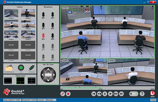
Orchid® Multimedia Manager operates in two different modes, synchronized or stand-alone:
Synchronized Mode: Orchid® Multimedia Manager operates in step with the simulation and receives all backtrack, store, and restore commands. The instructor can insert manual time markers by simply clicking the marker button within Orchid® Instructor Station. Markers are displayed on Orchid® Multimedia Manager’s progress bar, which also displays all replay points.
Stand-Alone Mode: Orchid® Multimedia Manager is manually controlled by the instructor for recording and playback. Once the sessions have been recorded, Orchid® Multimedia Manager can be used to replay the various sessions on a separate computer, typically for debrief sessions.
Orchid® Multimedia Manager’s advanced features and professional surveillance-grade interface make it easy to monitor and follow students during simulator training sessions. Its synchronization with the simulator makes debriefing sessions much more informative and helps instructors explain, and students understand, what actions and/or behaviors need to be corrected. Orchid® Multimedia Manager does away with standalone audio-visual recording systems and provides a valuable, simulation-synchronized teaching aid.
Benefits
Facilitates the implementation of the U.S. Nuclear Regulatory Commission’s recommendations regarding the video and audio recording (NUREG-1021, Rev. 10) (in relation to nuclear power plant simulators)
Fully synchronized with the simulation functions, such as freeze, run, restore, store backtrack, replay, etc. (no need for manual intervention to start and stop the recording)
Compatible with any simulation platform (L-3 MAPPS’ Orchid® platform or any third-party simulator platform)
Supports synchronized or standalone modes for debriefing with or without the full scope simulator
• Preview and/or playback available on any computer linked to the simulator network (instructor booth, debriefing room, etc.) with direct access to the recorded A/V
Debriefing capability outside the simulator network by using Orchid® Multimedia Manager client (or any commercial video viewer) from external media (flash disk or media device)
Flexible architecture supporting analog and/or digital cameras and microphones
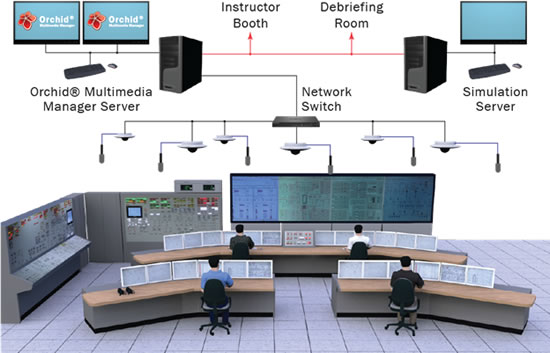
http://www.euronuclear.org/e-news/e-news-48/atomexpo-2015.htm
S. V. Kirienko, CEO of the State Atomic Energy Corporation, Rosatom, recently approved the Business Programme for the VII International Forum ATOMEXPO 2015, which will be held in Moscow, in Gostiny Dvor, from 1-3 June.
The main event of the Forum will be the Plenary Meeting, which will be dedicated to the following topic: Nuclear power engineering is the catalyst for social and economic development. Guests from many countries and congress participants will discuss the advantages of nuclear power engineering, its influence on social and economic development and the issues that would probably arise in the event of refusing to make use of nuclear energy.
The Plenary Meeting moderator will be Agneta Rising, the Director General of the World Nuclear Association (WNA). It is expected that the following people will take part in the meeting: Sergey Kirienko, CEO of the State Corporation, Rosatom; Filipp Knoche, Executive Director of Areva; Tim Yeo, Chairman of the Energy and Climate Change Committee at the lower Chamber of the UK Parliament; Khaled Tukan, Chairman of the Jordan Atomic Energy Commission; Vu Huy Hoang, the Vietnamese Minister of industry and trade; Tina Joemat Pettersson, the RSA Minister of Energy; Taner Yildiz, the Minister of energy and natural resources of Turkey; Takuya Hattori, the President of Japan Atomic Industrial Forum; William Magwood, Director General of Nuclear Energy Agency of the Organization for Economic Cooperation and development (NEA of OECD).
In the Forum’s Business Programme special attention is paid to international cooperation in the field on nuclear energy between the Russian Federation and countries from Latin America, the Asia-Pacific Region, Africa, and Central and Eastern Europe, as well as to discussions about Russian proposals for the development of its national energy programmes. In addition, a special session entitled: Atomic energy in BRICS countries will be devoted to addressing these issues.
During the Forum the following thematic round-tables are planned:
The role of NFC (nuclear fuel cycle) at the current state of nuclear power industry development
Economic effectiveness, security safeguards at implementation of referential decisions at the final stage of the life cycle of nuclear materials
Global nuclear engineering: Opportunities for global and local partnerships
The power engineering industry: cooperation at the worldwide market;
Integrated solutions for personnel training and nuclear infrastructure development within national nuclear programmes
NPP operation and maintenance: an up-to-date approach
New products for the nuclear engineering industry: trends and projects.
Funding of SC Rosatom projects: optimal format and requirements
At the venue for the VII International Forum ATOMEXPO 2015 there will also be a special exhibition featuring leading Russian and foreign companies in nuclear and related industries.
3,544 representatives of 600 organizations took part in the Business Program of the ATOMEXPO 2014 Forum, including 283 foreign companies from 42 countries.
More information is available about the 2015 event on the website at: www.2015.atomexpo.ru/eng/main
http://www.euronuclear.org/e-news/e-news-48/foratom.htm

FORATOM put together a detailed report on the latest situation with regards to greenhouse gas emission avoidance in the EU. After developing two hypothetical scenarios and estimations done by FORATOM it was concluded that the EU’s current nuclear fleet avoids around 680 million tonnes of CO2eq per year as compared to the emissions from a representative mix of fossil fuels generating the same amount of electricity. The amount of CO2 avoided by nuclear energy falls to around 450 million tonnes of CO2eq per year as compared to the emissions that would be produced by generating the same amount of electricity using all the other sources in the current (2014) energy mix. The full version of the FORATOM position paper on nuclear energy’s contribution to the EU’s Post-Kyoto climate change policy you can read here
For further information please contact Emilia Janisz at: 00 32 2 505 30 57; emilia.janisz@foratom.org
http://www.euronuclear.org/e-news/e-news-48/other-conferences.htm

17 - 21 May 2015
Makuhari Messe
Chiba, Japan
more

19 - 21 May 2015
Oxford Hotel, Oxford, United Kingdom
more
31 May - 3 June 2015
Saint John, NB, Canada
more

1 - 3 June 2015
Moscow, Russia
more

7 - 11 June 2015
Grand Hyatt San Antonio, San Antonio, TX, USA
more
17 - 19 June 2015
Delta Meadowvale Hotel and Conf. Centre, Mississauga,Ontario, Canada
more
22 - 25 June 2015
Paris, France
more

23 -25 June 2015
Trnava, Slovakia
more

2 - 5 September 2015
laguna Beach Resort, Sozopol, Bulgaria
more
![]()
14 - 17 September 2015
Portorož, Slovenia
more

23 - 25 September
A Coruña, Spain
more
19 - 21 October 2015
Ramada Parc Hotel, Bucharest, Romania
more
July 2016
Pittsburg, USA
more
http://www.euronuclear.org/e-news/e-news-48/Member-Societies.htm

Austrian
Nuclear Society |
Belgian
Nuclear Society |
Bulgarian
Nuclear Society |
Croatian
Nuclear Society |
Czech Nuclear Society |
Finnish
Nuclear Society |
French
Nuclear Energy Society (SFEN) |
German
Nuclear Society (KTG) |
Hungarian
Nuclear Society |
The
Israel Nuclear Society |
Italian
Nuclear Association |
Lithuanian
Nuclear Energy Association |
Netherlands Nuclear Society |
The Nuclear Institute |
Nuclear
Society of Russia |
Nuclear
Society of Serbia |
Nuclear
Society of Slovenia |
Polish
Nuclear Society |
Romanian
Nuclear Energy Association (AREN) |
Slovak
Nuclear Society |
Spanish
Nuclear Society |
Swedish
Nuclear Society |
Swiss
Nuclear Society |
http://www.euronuclear.org/e-news/e-news-48/Corporate-Members.htm
Links to ENS Corporate Members |
Aachen Institute for Nuclear Training GmbH |
Alpiq Suisse Ltd. |
Andritz AG |
Ansaldo Nucleare S.p.A |
AREVA NP GmbH |
Atomic Energy Council (AEC) |
Atomexpo LLC |
Atomtex SPE |
BKW FMB Energie AG |
Chilean Nuclear Energy Commisssion |
Electrabel GDF Suez |
NV Elektriciteits-Produktiemaatschappij
Zuid-Nederland EPZ |
E.O.N Kernkraft GmbH |
Electricité de France (EDF), Communication Division |
Elektroinstitut Milan Vidmar |
ENUSA Industrias Avanzadas SA |
EXCEL Services Corporation |
GE Hitachi Nuclear Energy International |
IEA of Japan Co. Ltd |
Kernkraftwerk Gösgen-Däniken
AG |
Kernkraftwerk Leibstadt AG (KKL), |
L-3 Communications MAPPS Inc. |
Linn High Therm GmbH |
MVM Paks Nuclear Power Plant Ltd |
NRG |
NUKEM Technologies GmbH |
ONET TECHNOLOGIES |
Paul Scherrer Institute |
SKB (Swedish Nuclear Fuel and Waste Management
Company) |
|
Studiecentrum voor Kernenergie, Centre d’Etude
de l’Energie Nucléaire SCK-CEN |
SVS FEM |
Synatom |
Teollisuuden Voima Oyj / Industrial Power
Company Ltd (TVO) |
Tractebel Engineering S. A. |
UNESA |
UniTech Services B.V. |
Urenco Limited |
Vattenfall AB |
VNS – Vinçotte Nuclear Safety |
VTT Nuclear |
Westinghouse Electric Company |
World Association of Nuclear Operators
(WANO), |
http://www.euronuclear.org/e-news/e-news-48/editorial.htm
Editorial Staff:
Mark O’Donovan, Editor-in-Chief
Contributors to this Issue:
Michael Ames (Massachusetts Institute of Technology)
M. Belal (South African nuclear energy corporation)
A.J. D’Arcy (South African nuclear energy corporation)
Noel Carmarcat (ENS)
David M. Carpenter (Massachusetts Institute of Technology)
Kirsten Epskamp (ENS)
Lin-wen Hu (Massachusetts Institute of Technology)
Emilia Janisz (ENS)
Gordon Kohse (Massachusetts Institute of Technology)
Mark O’Donovan (ENS)
Yakov Ostrovsky (Massachusetts Institute of Technology)
Alin Tatu (Romanian YGN)
D. Ridikas (IAEA)
Realisation:
Marion Brünglinghaus
Avenue des Arts 56, BE-1000 Brussels
Phone +32 2 505 30 50 - Fax: +32 2 502 39 02
E-mail: info@euronuclear.org - http://www.euronuclear.org
The ENS News is a quarterly publication, in electronic
form only.
Copyright notice ©2015 European Nuclear Society.
Reproduction is authorised provided that the ENS News is acknowledged as the
source – except where otherwise stated.
![]()
© European Nuclear Society, 2015