
ASSESSMENT OF THE BURNOUT PHENOMENON IN THE SAFARI-1
M. BELAL and A.J. D’Arcy
South African nuclear energy corporation
Church street west, Pelindaba, Pretoria 0001 - South Africa
ABSTRACT
The analysis of transients for the SAFARI-1 research reactor is done using the RELAP5/SCDAPSIM Mod3.4 system code, while the analysis of critical phenomena associate with the Critical Heat Flux (CHF) is done using available correlations within the code, such as the AECL look-up tables, or from literature such as Sudo and Mishima correlations discussed and applied in this work.
In this paper a proposal is made on the application of the Sudo scheme of correlations to predict CHF conditions, supplemented by the AECL look-up tables. The application was used to evaluate the low flow burnout phenomenon that may occur during the beyond design loss of flow accident.
In applying the scheme and during the course of the transient, various validity and applicability checks were made on flow patterns and heat transfer conditions. These conditions (e.g. hot channel exit equilibrium quality, flow pattern, rate of variation of the channel inlet flow rate, and range of the experimental data) were selected on the basis of RELAP5/SCDAPSIM modelling of the experimental rig used by Sudo, observations made by the experimentalists, and our understanding of the CHF mechanism associate with the burnout phenomenon.
In the analysis, the hot channel of the SAFARI-1 model was adapted to resemble the test rig used by Sudo. The model provides adequate simulation of the phenomenon and means for editing the required conditions mentioned above.
Moreover, the paper discusses the development and validation of the above-mentioned models to adequately apply the Sudo scheme, and presents comparisons with an unbounded (i.e. no condition check) application that would conclude a challenging condition to the fuel, as opposed to this work that concludes no physical burnout and the fuel remains intact during the course of the transient.
1. INTRODUCTION
In this work a Beyond Design Basis Loss of Flow Accident (BDBA LOFA) for the SAFARI-1 research reactor was selected as a case study to discuss the application of the Critical Heat Flux (CHF) scheme proposed by Sudo and Kaminaga[1]. Moreover, this work makes an attempt to apply the scheme within the range of applicability, physical and experimental. The physical are that established on the basis of assumptions made in deriving the correlations and the experimental are the range of conditions or observations made during the experiment.
The selected case study is a BDBA scenario that contemplates the loss of offsite power to the primary pumps, accompanied by a loss of emergency power to the shutdown pump i.e. total loss of forced convection, additionally the failure of any of the control rods to insert and shutdown the reactor, and assuming operator actions that worsen the course of the transient.
Such BDBA accident scenarios are used as a concept to develop the emergency operating procedures and also for the emergency planning and preparedness. On one hand a best estimate plus uncertainties is conventionally used and on the other hand best estimate analysis can be used to reveal phenomenon that is taking place to adequately establish the counter design or procedural provisions or actions to reduce the consequences, slowdown or eliminate the phenomenon.
The main objectives of this work are to identify model adequacy and aspects of future development for best estimate simulation of scenarios that may challenge the integrity of the fuel.
In section 2 we discuss the scheme and in section 3 we perform a pre-assessment of the BDBA LOFA transient to establish the region of interest for the comparison of RELAP5/SCDAPSIM Mod3.4[2] against the experiment. In section 4 we summaries the results of this comparison and validation. This validation assisted in establishing the adequate approach in applying the scheme and revealed aspects that should be considered for future development. These aspects are discussed in this paper.
2. THE CHF SCHEME PROPOSED BY SUDO
The CHF Scheme proposed by Sudo and shown in Figure 1 uses a dynamically set dimensionless mass flux that determines the correlation to be applied depending on the magnitude and flow direction. Figure 1 is divided into regions that depend on the dimensionless mass flux G*. The CHF in each region is respectively represented by equations 1 to 4 that is shown in the figure. When G*>G1* a difference in CHF is not observed between up-flow and down-flow and the CHF is well predicted by equation 4. When G2*<G*<G1* the CHF is predicted by equation 2 for down-flow and when G3*<G*<G1* the CHF is predicted by equation 1 with ∆T*SUB,o=0 for up-flow. When G*<G3* for both up-flow and down-flow the mass flux is very low or the flow condition is a counter-current flow, the CHF is predicted by equation 3. Moreover in this figure the blue line refers to up-flow directions and the red lines refers to down-flow direction, while the green line refers to both up-flow and down-flow directions. The red dotted line represent the summation of Equ.2 and Equ.3 that is originally developed by Mishima[3] and modified for applications by Sudo.
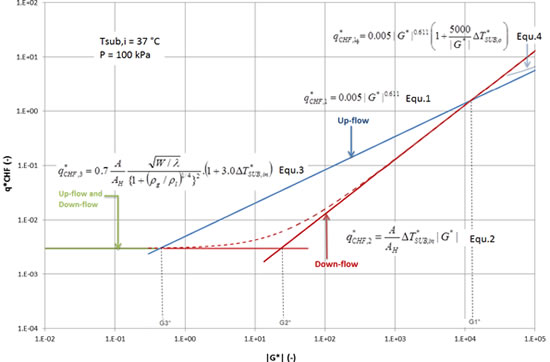
Figure 1: Sudo and Kaminaga CHF Scheme
where:
| A |
:flow area of channel, m2 |
AH |
:heated area of channel, m2 |
q |
: heat flux, W/m2 |
q* |
: dimensionless heat flux = q" / hfg√ [λ ρg(ρl- ρg)g] |
W |
:width of channel, m |
G* |
:dimensionless mass flux = G / √ [λ ρg(ρl- ρg)g] |
λ |
:characteristic length |
∆TSUB,in |
:sub-cooling for channel inlet, ˚C |
∆T*SUB,in |
dimensionless sub-cooling for channel inlet = Cp ∆TSUB,in/hgf |
∆T*SUB,o |
:dimensionless sub-cooling for channel outlet |
ρg, ρl |
:vapour and liquid densities, kg/m3 |
Cp |
: specific heat capacity, J/kg.K |
hfg |
:latent heat of evaporation, J/kg |
|
|
In the above correlations; Equ.1 and Equ.4 are correlated to the experimental data[1], Equ.2 was derived assuming zero exit equilibrium quality[3], and Equ.3 is derived from the heat and mass balance[3] in the heated section and the flooding condition by Wallis[4]; Moreover, the parameters that dominated the resultant value of CHF is the mass flux G* followed by the channel inlet sub-cooling ∆T*SUB,in; while the values of channel configuration, namely, A, AH and W, are apparently fixed for the configuration under evaluation as shown in Table 1 of section 4 below. All other parameters are evaluated at the saturation conditions at the channel inlet.
The dimensionless mass fluxes Gi* (i=1..3) are the boundaries between the regions shown in Figure 1 and are calculated and defined as follows[1]: 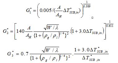
These dynamically calculated mass fluxes are compared with the actual mass flux in the hot plate channel, in terms of both magnitude and flow direction, to determine the applicable correlation (Equ. 1 to Equ. 4) to be used.
3. DBA and BDBA LOFA pre-ASSESSMENT
During the course of the DBA and BDBA LOFA the inlet sub-cooling varies between about 10°C and 80°C (80°C is the inlet sub-cooling during normal operation at 20 MW). Figure 2 is an extract of Figure 1 at the above inlet sub-cooling values where only the red and green lines are affected. The figure also superimposes the evolution of the hot channel dimensionless mass flux and heat flux during the course of the DBA and BDBA LOFA.
The main region of interest is highlighted when the mass flux G*(t) coincide with the heat flux q*(G*) that exceeds the predicted CHF (i.e. excess of CHF is mainly above the 10 °C inlet sub-cooling line which happen only in few instances during the transient as shown in Figure 3). This region of interest is used only for the comparison and validation of the RELAP5/SCDAPSIM model and to establish the adequate application of the scheme, knowing the procedure and steady conditions used during the experiment when compared with the steep variations in the actual transient. Nevertheless in safety analysis the margin to acceptance criteria should be considered which may reduce the lines shown in the figure by this criterion.
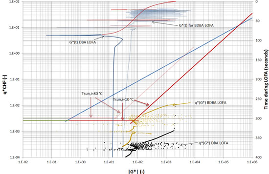
Figure 2: Extraction of CHF correlations of Figure 1 at 10°C and 80 °C of inlet sub-cooling, showing the DBA and BDBA LOFA actual dimensionless mass flux G*(t) and actual dimensionless heat flux q*(G*) and the region of interest.
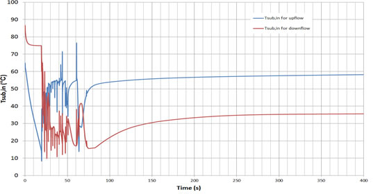
Figure 3: Inlet Sub-cooling during the BDBA LOFA for up-flow and down-flow
4. MODEL ASSESSMENT AND VALIDATION
The CHF and the application of the Sudo scheme does not depend only on the G* value and configuration but also on a set of CHF operating parameters that are correlated empirically in the range of parameters tested, and on the mechanism of the CHF observed[5]. The main CHF operating parameters are the flow pattern, the channel exit conditions and the range of the experimental data.
In order to establish the CHF operating parameters mentioned above and to validate the application of the scheme, a comparison is made between the experiment conducted by Sudo and Kaminaga and the behaviour of RELAP5/SCDAPSIM code system. Figure 4 shows the SAFARI-1 core nodalization (left) and the RELAP model of the hot channel that resembles Sudo and Kaminaga experiment (right). Table 1 presents the model parameters used for the comparisons and also the key parameters of the experiment. The validation was focused on the range of mass and heat fluxes that represent the region of interest identified in section 3 above.
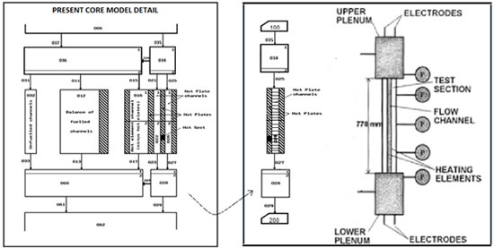
Figure 4: SAFARI-1 core nodalization (left) and RELAP model that resembles Sudo and Kaminaga experimental rig (right)
Table 1: Validation, Model and Operating Parameters
Model configration |
|
|
|
Flow channel width |
(mm) |
50 |
034 |
Inlet plenum |
Flow channel length |
(mm) |
750 |
026 |
Coolant channel |
Water gap width |
(mm) |
2.25 |
028 |
Outlet plenum |
Heated element width |
(mm) |
40 |
Heated element length |
(mm) |
750 |
100,
200 |
Inlet subcooling and pressure controls |
Operating parameters |
|
|
Inlet subcooling |
(°C) |
37-39 |
|
Flow direcition |
- |
Upflow, downflow |
|
Flow rate |
(Kg/m2s) |
0 – 25,100 |
|
Heat input |
(kW) |
Up to 0.1MW |
|
Pressure |
kPa |
100 – 120 |
|
The procedure for comparison at each G* value was as follow:
-
Obtain the predicted CHF at cold condition (i.e. P=1Watt) and at the inlet sub-cooling and system pressure shown in table 1,
-
Assign power to the hot plate in steps (about 60 s each) until a sharp increase in the surface clad temperature is obtained,
-
Assess the RELAP behaviour as the condition approach the CHF and at the CHF.
In RELAP model that resembles the experiment; twenty axial nodes were made to compare with the thermocouples used in the experiment. This is due to the fact that at certain conditions, and specifically for non-uniform heat flux distribution, the CHF and the sharp temperature increase can take place away from the hot-spot. Moreover, the models and correlations that govern the energy and momentum closure relations and special flow process models were varied to identify aspects that affect the comparison. Amongst these models the interphase friction, wall drag and the Counter Current Flow Limitation (CCFL) model of Wallis affect the comparison within ±10%. The dominant closure relation that derives the comparison is the wall-to-fluid heat transfer (i.e. the transition between heat transfer mechanisms and the application of the corresponding heat transfer correlation).
Figure 4 is an extract of Figures 1 and 2 showing results of the comparisons. The initial comparison (red triangles) were performed using RELAP model without special adjustments. Figure 5 shows a case during one comparison run. In this case the CHF predicted by AECL look-up table[6] and by Sudo scheme is shown. According to Sudo scheme the transition to transition or film boiling should take place at 650 s (see black arrow in Figure 5) when the actual heat flux exceeds Sudo predicted CHF, while the AECL CHF, that is implemented in RELAP5/SCDAPSIM, is orders of magnitude higher.
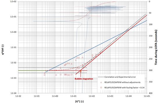
Figure 4: Comparison of Sudo and Kaminaga experiment and RELAP5/SCDAPSIM Mod 3.4 code.
As mentioned above that the dominante model that derive the comparison is the heat transfer logic while others provide ±10% variation, the adjuestment was done by selecting a foulding factor of 0.14 that reduces the heat transfer coefficients and the CHF solution. This adjustment, even if not adequate, was reasonable to study the impact of the transition logic in the comparison. The results are presented in Figure 4 (red rectangulars) which show the same trend as in the Sudo scheme. A slightly higher fouling factor can bring the comparison within the experimental error however it was found unnessary at this stage.
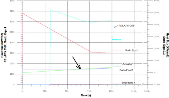
Figure 5: A sample of a comparison case showing the flow transition logic from nucleat boiling to transition or film boiling that depend on the CHF correlation implemented in the logic
The adjusted results were used to establish the conditions used to applying the Scheme and during the course of the transient. 0 shows the actual operating parameters stated by Sudo for equation 1 and 4[1], and by Mishima for equations 2 and 3[3], and the assumed operating parameters derived from the model validation and used in this analysis.
Table 2: Actual and conservatively assumed CHF operating parameters
Operating parameter |
Actual |
Assumed |
Xe,o(-) |
~<0 |
≥-0.02(1) |
Flow pattern (-) |
≥ANM |
≥SLG(2) |
Flow rate differential (kg/m2.s /s) |
~0 |
≤2.5e-03(3) |
Mass flux (kg/m2.s) |
-600 to +480
-610 to +360 |
-600 to +480(4)
-610 to +360(5) |
Heat flux (MW/m2) |
Up to 1.3 |
Up to 1.3(6) |
-
This criterion is applied to equation 2 since it was derived from the condition Xe=0 (the negative qualities refer to sub-cooled conditions). The '~<0' was recommended due to the presence of unheated side walls. The conservatively assumed equilibrium quality corresponds to about 10-15 °C exit sub-cooling.
-
This criterion is applied to equation 3 and is based on the flow patter associated with the high quality flow burnout mechanism [1,3,5].
-
This criterion is applied to equations 2 and 3 as noted by Mishima[3]: “The results are obtained for steady inlet-flow condition and may be valid also for a slow transient”. The assumed value is the maximum variation during the flow reversal as derived from DBA LOFA. This criterion was also selected to study the influence of the timely behaviour required for the CHF condition to establish.
-
The range of the experimental data for equations 1. Outside this range the AECL based DNBR is used.
-
The range of the experimental data for equations 2 and 3. Outside this range the AECL based DNBR is used.
-
The range of heat fluxes for equations 2 and 3. Outside this range the AECL based DNBR is used.
Figure 6 shows the Burnout Ratio (BOR) and the inline application of Sudo scheme (via RELAP control variables) when conditions of Table 2 is not applied while Figure 7 shows the BOR when conditions of Table 2 is applied. From Figure 7 it could be argued that the adequate application of Sudo Scheme within the range and conditions of the experiment shows sufficient margin to burnout and the fuel stay intact during the course of this transient.
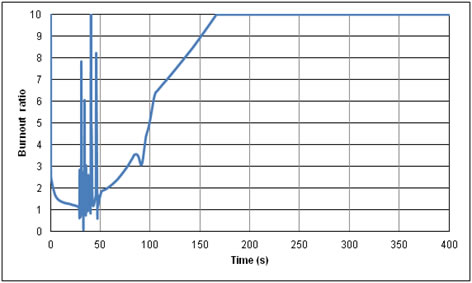
Figure 6: Burnout Ratio during the course of BDBA LOFA with unbounded application of Sudo Scheme
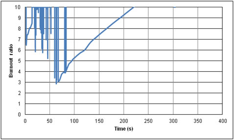
Figure 7:Burnout Ratio during the course of BDBA LOFA with a bounded application of Sudo Scheme
5. Conclusion
A detailed validation was performed of RELAP/SCDAPSIM Mod 3.4 against Sudo and Kaminaga experiment for the prediction of the CHF condition in a rectangular flow channel. This validation has identified the main drive of the comparison and the adequate application of the Scheme. The comparison was driven by the criteria used for the transition between heat transfer mechanisms to up to a factor of 5 while various models governing the two phase flow momentum and energy transfer vary the comparison with ±10%.
An adjustment was made to study the impact of the criteria used for the transition between heat transfer mechanisms which resulted in a better agreement with the experiment. The adjusted comparisons are used to establish the conditions of applicability of the Scheme.
The application of the Scheme, within the region of applicability, and during the course of beyond design basis loss of flow accident, showed a sufficient margin to burnout as opposed to deteriorating behaviour if the Scheme was applied outside its region of applicability.
6. References
[1] M KAMINAGA, K YAMAMOTO and Y. SUDO, "Improvement of Critical Heat Flux Correlation for Research Reactors Using Plate-Type Fuel", Journal of Nuclear Science and Technology, Vol.35, No.12, p. 943-951, December 1998
[2] RELAP5/MOD3.3Beta Code Manual, "Models and Correlations", VOLUME IV, section 4.2.3.5, page 135.
[3] MISHIMA, K., "Boiling burnout at low flow rate and low pressure conditions, Dissertation Thesis", Kyoto Univ., (1984).
[4] Wallis, G.B.:”One-dimensional Tow-phase Flow”, (1969). McGraw Hill.
[5] L.S.TONG, Y. S. Tang, "Boiling Heat Transfer and Two-Phase Flow", 2nd Edition, para.5.2.3, 1997.
[6] D. C. Groeneveld, S. C. Cheng, and T. Doan, "1986 AECL-UO Critical Heat Flux Lookup Table", Heat Transfer Engineering, 7, 1-2, 1986, pp. 46-62.
|