
STATUS OF THE FLUORIDE SALT HIGH TEMPERATURE REACTOR MATERIALS IRRADIATION TESTS AT THE MIT RESEARCH REACTOR
David M. Carpenter, Michael Ames, Yakov Ostrovsky, Gordon Kohse, Lin-wen Hu
Nuclear Reactor Laboratory
Massachusetts Institute of Technology
Abstract – The first irradiation test of structural materials and surrogate TRISO fuel particles in a molten, fluoride-based salt was completed successfully at the Massachusetts Institute of Technology Research Reactor (MITR). The irradiation test is part of an ongoing joint research program being conducted at MIT, the University of California-Berkeley (UCB), and the University of Wisconsin-Madison (UW). The objective of the overall research program is to develop a path forward to a commercially viable, fluoride-salt-cooled, high-temperature reactor (FHR). The baseline FHR concept combines a fluoride salt coolant called flibe (a mixture of LiF and BeF2), with a graphite-matrix, coated-particle fuel. The objectives of the first FHR irradiation experiment at the MITR are: (1) to assess the corrosion and compatibility of 316 stainless steel, Hastelloy N®, SiC and SiC/SiC composites, and surrogate TRISO fuel particles in molten flibe, and (2) to examine the partitioning of tritium (produced when the flibe is subjected to neutron irradiation) among the various media in the experiment. This irradiation was performed with flibe temperature at 700°C which marks the first demonstration of flibe irradiation capability at the MITR. Initial results provide evidence of the high potential mobility of tritium in an FHR system consisting primarily of liquid flibe, graphite, and high-nickel alloys at high temperature. At the same time, a large percentage of the tritium that was predicted to have been generated in the salt was not detected in the gas phase, mirroring experience from the MSRE and indicating a potential for tritium control through tritium capture in solid components. Fast neutron activation products 16N (t1/2 = 7.1 s) and 19O (t1/2 = 26.9 s) were measured and shown to be significant radiation dose contribution in the gas phase. Post-irradiation examination of irradiated materials is ongoing and will attempt to identify if the tritium balance can be accounted for by tritium absorption in the salt, the specimens, and the capsule’s structural materials. Measurements of the corrosion rates of SiC, SS316, and Hastelloy N coupons has shown that all three are susceptible to some corrosion in the salt, with higher rates when coupled with nuclear-grade graphite. In addition, surrogate TRISO particles exposed directly to flibe appear to have increased susceptibility to radial cracking after irradiation and salt freeze-melt cycling.
I. Introduction
The Fluoride-Salt-Cooled High-Temperature Reactor (FHR) concept is the subject of an ongoing three-year U.S. Department of Energy-funded Integrated Research Project (IRP), which aims to develop the “path forward” to a salt-cooled test and commercial power reactor. This IRP is led by the Massachusetts Institute of Technology (MIT) in partnership with the University of California, Berkeley and the University of Wisconsin-Madison (UW).1
The FHR baseline concept is a fluoride-salt-cooled, graphite-moderated pebble-bed reactor with 600°C inlet and 700°C outlet coolant temperatures. The lithium-beryllium fluoride salt primary coolant (67%LiF-33%BeF2), known as flibe, was chosen because of its favorable characteristics as a high-temperature, low-pressure heat transfer fluid that is optically transparent and has good neutronics properties.
The FHR concept is based on experience from the Molten Salt Reactor Experiment (MSRE), which operated at Oak Ridge National Laboratory (ORNL) between 1964 and 1969.2 The MSRE used a fueled salt in its primary loop (ZrF4-UF4 was added to the flibe). In contrast, the FHR takes advantage of recent coated particle fuel (TRISO) technology to provide compatibility between TRISO/graphite fuel compacts and the liquid flibe, isolate the fuel from the salt, and maintain a “clean” primary coolant.3
The combination of flibe coolant, TRISO compact fuel, and a graphite core structure allows the FHR to achieve a large thermal margin to core damage. The boiling point of the flibe is 1430°C, and the failure temperature of the graphite and TRISO particles is above 1600°C. With an outlet temperature of 700°C the FHR has a substantial temperature safety margin compared to existing light water power reactors.
Proposed materials for other structural components of the FHR design are 316 stainless steel (SS316), Hastelloy® N, carbon-fiber composites (CFCs), and silicon carbide fiber composites (SiC/SiC). Hastelloy N was developed specifically for use with liquid salt and has excellent corrosion resistance at the temperatures of interest, as was demonstrated in the MSRE. However, as a specialty metal Hastelloy N has limited commercial production and is not code-qualified as a vessel structural material for reactor operation at FHR conditions. Therefore this IRP is investigating the possible use of SS316 as a well-characterized and economical replacement. CFC and SiC/SiC materials have seen substantial development and improvement in quality in the last few decades, with increasing interest in their use in both fusion and fission reactor environments. In the FHR, these ceramics are being considered for the core barrel and as control element and instrumentation channel liners, which are structures in high-radiation areas that do not need to be as stringently code-qualified (e.g. are not classified as pressure vessels).
II. EXPERIMENT DESIGN
An irradiation test including the flibe and proposed FHR structural materials has been designed, built, and carried out at the MIT Nuclear Reactor Laboratory (MIT-NRL) utilizing the MIT Research Reactor (MITR). The purpose of this irradiation was threefold: (1) to demonstrate the ability to implement a flibe-bearing materials test at 700°C in the MITR; (2) to measure the transport and disposition of tritium produced in the flibe; and, (3) to evaluate the corrosion of TRISO and FHR structural materials exposed to flibe at 700°C during neutron irradiation.
The MIT test was carried out at the NRL in parallel with non-irradiated autoclave tests which took place at UW. The UW and NRL tests utilized an identical test matrix with the specimens and specimen holders sourced from the same materials and prepared at the same location. The main purpose of these initial parallel tests is to isolate the effects of irradiation damage and other irradiation-induced effects such as tritium generation on the test results and to help to determine what further irradiation experiments are required for initial FHR development.
Furthermore, this irradiation represents the first attempt to irradiate significant amounts of flibe under active temperature control at the MITR.
II.A. MITR ICSA Facility
The MITR is a 6 MW, light water-cooled, heavy water-reflected tank-type research reactor. The MITR has a compact, HEU core with plate-type fuel in rhomboidal assemblies arranged in three concentric rings. Of the 27 in-core element positions, three (two in the central ring, one in the middle ring) are dedicated for in-core experimental facilities. The neutron flux available to experiments in-core is up to 3.6x10¹³ n/cm2-s thermal and 1.2x10¹⁴ n/cm2-s fast (E>0.1 MeV) when the reactor operates at full power, with a spectrum similar to that of a light-water reactor.
The MITR’s primary coolant is light water at atmospheric pressure and an outlet temperature of about 50°C. The free space available in-core for a single experiment is approximately 5 cm in diameter and 56 cm in height. These constraints require the use of special facilities in order to achieve the desired test conditions. For this initial irradiation the target conditions are a constant 700°C exposure for 1000 hours under inert cover gas.
The irradiation utilized the In-Core Sample Assembly (ICSA) facility installed in one of the central-ring core positions. The ICSA is a general-purpose irradiation facility, which has been approved and demonstrated for capsule irradiations up to 900°C.4 The ICSA outer thimble is a titanium tube with a 5 cm outer diameter and S-bend shape that extends from just below the reactor top shield lid, four meters down to the bottom of the core. The S-bend shape prevents direct radiation streaming up through the core tank. Connections at the top of the thimble and integral gas lines along its side allow for gasses to be continuously injected into the ICSA at the bottom of the core and exhausted from the top of the thimble. Experimental test components in the ICSA are contained in metal capsules that are inserted from the top of the ICSA. ICSA capsules are typically about 4.5 cm in diameter and 15 cm long. Several different capsules can be stacked within the in-core region.
Heating in the ICSA is accomplished passively, primarily utilizing gamma heating of high-Z materials. Heat is rejected from the system across the gap between the capsules and the thimble, and then into the MITR’s primary coolant. Through careful design of the irradiation capsules and radial gas gaps, temperatures of up to 900°C are readily achievable. While the gross ICSA capsule temperature is controlled by reactor power and capsule design, fine control of temperature is achieved by varying the gas mixture in the thimble. To operate the ICSA at the lowest temperature, the thimble is filled with 100% helium; in order to increase temperature, neon (which has a lower thermal conductivity than helium) is added. The demonstrated temperature control range that can be achieved by varying the helium/neon mixture is about
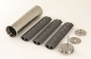
Fig. 1. Components of the experiment capsule prior to assembly. Left-to-right are the outer nickel capsule, the three sections of the graphite sample and flibe holder, and, top-to-bottom on the right, the bottom graphite support/spacer, the top cover plate, and the capsule lid (without thermocouples and gas lines).
450°C as demonstrated during ICSA testing at 5 MW, although this will vary somewhat depending on the absolute temperature and capsule geometry.
II.B. Capsule Design
The irradiation capsule for this experiment, components of which are shown in Figure 1, was designed to meet the experiment’s thermal requirements, allow independent sampling of the capsule and thimble gases, and protect the ICSA from exposure to the salt or its corrosive byproducts. The outer capsule was constructed from Alloy 201 nickel except for the top threaded section and lid which are Inconel® 800H. These materials were chosen for their high-temperature strength and resistance to flibe and HF corrosion. HF may be produced from the flibe if it comes into contact with moisture or as a result of tritium generation (TF). These metals also provide a good susceptor for gamma heating of the capsule internals and are sufficiently resistant to neutron irradiation for the purposes of the 1000-hour test.
Inside the capsule is a three-section graphite sample holder, shown in the center of Figure 1, machined from IG-110U, a high-purity, isotropic graphite manufactured by Toyo Tanso. The graphite provides compatibility with the flibe, excellent thermal conductivity (providing a uniform temperature distribution), and is part of the test matrix for corrosion and tritium interactions. There are six vertical chambers machined into the graphite, 1 cm in diameter and 14.5 cm deep, where the salt and specimens reside. A nickel disk rests on top of the graphite and a thin nickel base plate supports the graphite above the bottom of the capsule. This arrangement is designed to produce a small vertical temperature gradient in the capsule, ensuring that
TABLE I
Specimen Test Matrix
Graphite Chamber |
Liner |
Specimens |
A |
none |
2 Hastelloy N plates |
B |
none |
2 SS316 plates |
C |
none |
3 SiC/SiC, 1 SiC |
D |
none |
~300 TRISO particles |
E |
SS316 |
2 SS316 plates |
F |
Hastelloy N |
2 Hastelloy N plates |
the salt melts from the upper free surface downwards to prevent damage to the graphite holder from flibe expansion during the phase transition.
The capsule’s lid has penetrations for two gas tubes and three nickel rods (all Inconel 600). The gas tubes allow the helium cover gas in the space above the flibe to be sampled and refreshed. The nickel rods were brazed into the lid and extend down into the graphite holder; their extra mass is used to assist with melting the flibe from the top down. Thermocouples run through two of these rods, and the thermocouple tips sit in the graphite at the half-height of the capsule between chambers. The lid threads into the lower capsule and seals it by compressing an Inconel 718 C-ring.
The specimen test matrix is given in Table I. Two of the chambers, E and F, were lined with metal – the flibe and specimens in these chambers are not exposed to graphite. All of the metallic specimens are rectangular coupons (25 mm x 6mm x 0.5 mm), which hang on wires made from the matching metal and are secured through small holes in the nickel disk above the graphite. The SiC and TRISO specimens sit freely at the bottom of their chambers.
Assembly of the capsule took place in three main steps. First, the capsule parts were manufactured from nickel and graphite, and the gas tubes, thermocouples, and nickel pins were brazed into the capsule lid.
Second, the loading of the flibe and specimens into the graphite chambers was performed inside an argon-filled glove box at UW using the same process and equipment used to load the flibe and specimens for the parallel UW autoclave test. Immediately prior to the loading the graphite sections and liners were heated at 800°C in an argon-10%-hydrogen atmosphere for 24 hours. This process removes oxygen and moisture that may be adsorbed on the surfaces of the components – such a surface preparation process is important for any equipment to be used with liquid flibe. After all of the specimens were placed in the graphite chambers, flibe was dripped slowly into each chamber directly from a heated storage container until the chamber’s target mass was achieved. The flibe loadings in each chamber are given in Table II.
After loading the specimens and flibe into the chambers, the graphite was inserted into the nickel capsule, the capsule was closed with a temporary blank lid, and the closed capsule was then sealed into a secondary container for shipping back to MIT. All of sealing at UW was done inside an argon-filled glove box.
Final assembly took place at MIT. The capsule, with temporary lid, was placed in a circulating helium-filled glove box where the lid was removed. The full capsule was held at 250°C for five hours before the final lid (with thermocouples and gas lines) was sealed on. The capsule was then inserted into the ICSA tube in the reactor and immediately connected to gas lines for helium purging while cold.
A neutronics analysis of the ICSA experiment was performed using the MCNP-5.1.4 code and a 3D representation of the MITR core. This calculation predicted axial-average neutron fluxes of 2.35x10¹³ n/cm2‑s thermal and 1.16x10¹⁴ n/cm2-s fast (E>0.1 MeV) in the salt chambers with the reactor at a power of 6 MW. Using this code the gamma heating rates of the graphite and nickel structural materials in the capsule and the titanium ICSA tube were also estimated. These data were fed into the ANSYS Fluent v13 computational fluid dynamics code for calculation of the temperature distribution inside the experiment. This process was used iteratively during the design phase to fine-tune the proper dimensions for the capsule wall in order to achieve the target 700°C in the salt chambers.
For the Fluent analysis, a 3D capsule model and a 13-inch high section of the ICSA tube was converted and meshed using the ANSYS meshing tools. This analysis modeled the flibe physically as a solid with the thermal properties of the liquid at 700°C. It also considered the gas flow in the outer ICSA tube, but not within the capsule (the capsule gas space was modeled as a heat sink, removing the small amount of energy calculated to be lost to the cold helium flowing at 50 cc/min). The initial analysis considered two extreme conditions for the outer ICSA thimble gas with the reactor operating at 5.9 MW: (1) 100% helium gas flow, and (2) 100% neon gas flow (both at 100 cc/min). In both cases the capsule internal gas remains pure helium. The simulation results are shown in Figure 3; the maximum predicted temperature in the sample chambers is 760°C with 100% helium and 1130°C with 100% neon.
TABLE II
Flibe Loading
Graphite Chamber |
Flibe Mass (g) |
A |
21.3 |
B |
21.2 |
C |
21.2 |
D |
21.2 |
E |
18.2 |
F |
18.1 |
II.C. Salt Preparation
The flibe salt used in the MIT irradiation and the UW autoclave test was procured from Oak Ridge National Laboratory. This salt is from the supply of flibe for the secondary coolant loop of the MSRE and has been in storage since that reactor’s decommissioning. The flibe used in the primary and secondary systems of the MSRE was enriched in 7Li because of the unfavorable 6Li(n,α)3H reaction, which has a large, 940 b thermal cross section. 6Li, which is 7.5% abundant in natural lithium, is therefore both a neutron poison and a substantial source of tritium. To counter this, the MSRE utilized 99.995% 7Li enriched flibe in its fueled primary loop, and 99.99%
7Li enriched flibe in its clean secondary loop and flush systems.5 However, even if 6Li were removed entirely from the flibe, an equilibrium level of 6Li will be reached due to generation from the 9Be(n,α)6He reaction, so flibe will always be a significant tritium generator. Smaller amounts
of tritium are also produced in flibe by the 19F(n,t)17O and 7Li(n,n+t)4He reactions.
Flibe must be handled carefully and kept in a dry, inert environment as the salt will readily absorb moisture. It is a strong oxidizer, and will react with metal oxides (e.g. surface layers) to form metal fluorides. At elevated temperatures the salt will decompose in the presence of H2O to form HF and BeO.6 In turn, if the HF becomes hydrated, it will form hydrofluoric acid that can easily etch glass and steel surfaces.
The salt from the MSRE has been stored at ORNL in sealed steel containers for over 40 years. This, combined with our assessment that there may have been little or no chemical cleanup of the MSRE secondary system (metal corrosion product buildup was detected during reactor operation), presented the possibility of contamination of the MSRE flibe with various trace elements. It is likely this MIT irradiation represents the first time this enriched flibe has been analyzed, or irradiated, since the 1960’s.
The flibe used in this experiment was transferred at ORNL into smaller stainless steel containers using a heated, sealed, and pressurized loading system, and then shipped to UW. At UW the salt was re-melted and extracted from the shipping container, and then purified to remove moisture and oxides and to reduce the presence of trace metals. In short, the flibe was first melted in the presence of metallic beryllium and sparged with argon and hydrogen gasses. Next, a 1:10 by volume mixture of hydrogen and hydrogen fluoride gas was bubbled through the liquid salt for 1.5 hours, followed by 24 hours of sparging with H2. Samples of the flibe before and after this purification were sent to the MIT-NRL for neutron activation analysis (NAA). Although there was no explicit salt purity standard in place for this experiment, the original impurity standards for the MSRE primary flibe were used as
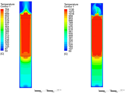
Fig. 2. Fluent calculation of experiment capsule with (left) 100% helium thimble gas, and (right) 100% neon thimble gas at 5.9 MW reactor power.
a point of reference. The NAA analysis found that the UW purification process did help to reduce the amount of trace metals in the flibe; however, levels of Al and Cr remained slightly above the MSRE impurity standard (173±19 ppm vs. 150 ppm Al and 36±1 ppm vs. 25 ppm Cr), and levels of manganese and nickel are still undetermined.7
Other than this initial purification and NAA, there was no active effort to control or monitor the redox potential of the flibe during the experiment. This was done in part because the optimum redox potential for the FHR had not yet been decided, but this also allowed design simplification for this initial demonstrative irradiation (and the parallel UW tests).
III. IRRADIATION EXPERIMENT
The ICSA and experiment capsule were installed in the MITR on September 10, 2013. A schematic of the ICSA gas system for this test is shown in Figure 4. The basic layout consists of three parallel gas supply systems regulated by mass flow controllers – one helium and one neon system to the ICSA thimble, and one helium system to the experiment capsule (the emergency helium system floods the thimble in the event of an over-temperature condition). The main helium gas flows are intended to be constant during the experiment; the neon mass flow into the thimble, however, is generally controlled manually or from a PID temperature controller that receives feedback from one of the two capsule thermocouples (TC 1). Because of the sensitivity of the flibe to contamination, an oxygen gettering furnace with a zirconium element is used on the helium supply gas to the capsule to help remove any traces of oxygen. Gas pressure is monitored at the inlet to the ICSA tube and capsule independently on the helium and neon lines, and controlled with a backpressure regulator at the outlet of the thimble and capsule. Helium and neon are supplied independently and mixed at the bottom of the ICSA thimble in order to decrease the response time between adjusting the neon flow rate and achieving a change in the gas mixture in the in-core section.
The outlet gas from either the thimble or the capsule can be directed through a train of instruments including a Dycor® LC Series residual gas analyzer (RGA), Overhoff Technology Corp. TASC tritium bubbler, and Omega Engineering Inc. PHE-4201 pH probe contained in a dedicated water bubbler. The exhaust gas is then directed through a charcoal filter before being mixed into the reactor building’s ventilation system for monitoring and exhaust. The experiment exhaust line not being monitored by the instrument train runs directly into the charcoal filter.
After installation of the capsule into the ICSA thimble the gas system operated at ambient temperature and 100 cc/min helium gas flow through the thimble (100 kPa) and capsule (135 kPa) for three days in order to remove air and moisture before heating the capsule. Levels of both air (monitored as nitrogen) and water were evaluated using the RGA on the gas exhaust system.
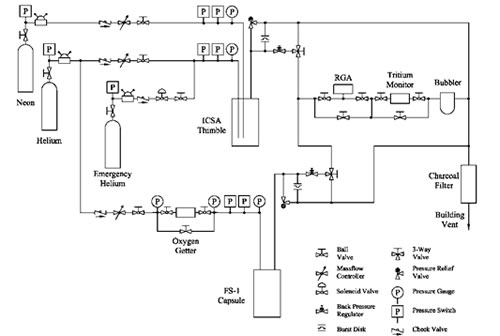
Fig. 3. Schematic layout of the ICSA gas system with the experiment capsule (labeled FS-1).
On September 13 the reactor was started and its power was raised in 500 kW steps with 20 minute stabilization periods up to a power of 2 MW, at which power the capsule temperatSure reached 290°C. The temperature was held there to allow any additional moisture to be evolved from the system.
While holding at 2 MW, a higher than expected level of radioactivity was observed near the capsule outlet tubing. Analysis of the radiation’s gamma spectrum using a portable HPGe detector (Canberra Falcon 5000®) determined the primary contributors to be 16N (t1/2 = 7.1 s, primary Eγ = 6.129 MeV) and 19O (t1/2 = 26.9 s, primary Eγ = 197.1 keV and 1.357 MeV). These isotopes were being produced from fast neutron reactions on 19F ((n,α) and (n,p), respectively) and were then escaping the flibe into the capsule cover gas. It was not clear if the rate at which these gases were being released at this time was controlled by reactions at the salt’s free surface or by diffusion through the solid (though possibly porous) flibe. On September 16 reactor power was briefly lowered to 50 kW for adjustments to the capsule exhaust line. The length of exposed tubing in the capsule gas outlet line was reduced, a radiation monitor (GM tube) was placed immediately next to it, and a delay volume surrounded by 8 inches of lead shielding was installed.
It is interesting to note that the production of 16N and 19O in the flibe was not mentioned in the ORNL reports on their MSRE experience, likely because of both the short half-lives of these isotopes and the presence of many other highly radioactive fission products in the MSRE primary salt. In contrast, this experiment’s salt contained few other radioisotopes. Also, the sweep gas transit time from the reactor core to the measurement location was on the order of one second. These isotopes were not detected in the ICSA thimble exhaust gas because: (1) they have no ready path into the thimble gas space, and (2) if they were present in-core, the transit time through the upper portions of the thimble is on the order of ten minutes. It should also be noted that while 16N and 19O isotopes are produced in water-cooled reactors (from neutron reactions with stable oxygen isotopes), on a curies per gram coolant basis, the production of 16N is hundreds and of 19O thousands of times higher in flibe than in H2O (calculated using ORIGEN-S with the MITR neutron spectrum).
On September 17 reactor power was again increased in 500 kW steps. At 3.5 MW reactor power was held and the capsule temperature reached 425°C. Neon was then introduced into the ICSA thimble to slowly raise the capsule temperature through the flibe melting point (459°C). The ICSA gas system was held at 20 cc/min neon, 80 cc/min helium with the capsule at 470°C before reactor power was again increased in 500 kW steps. At 5.5 MW the capsule reached 640°C; helium flow was decreased and the neon flow was manually increased before regulation was turned over to the automatic PID controller. With a helium flow of 60 cc/min, the neon flow rate settled at 32 cc/min in order to hold the capsule temperature at 700°C.
As shown in Figure 4, the experiment ran without interruption and at constant reactor power for the next 1000 hours, with variations in the controlled neon flow rate of ±2 cc/min and temperature of ±1°C from one thermocouple and ±3°C from the second, noisier thermocouple (this noise may be in part due to the first thermocouple being transmitted as a voltage and the second as a current loop).
Temperature, pressure, and flow rate data were monitored at 2 Hz by the data acquisition system, while RGA data was taken approximately once per minute and tritium samples were collected for 24 to 72 hours between exchanges.
While the reactor power remained constant, the capsule gas mass flow rate also remained constant. Only 16N and 19O were definitively measured in the capsule outlet gas (41Ar was also detected in the gas, presumably due to activation of trace argon in the helium supply, but it was difficult to distinguish from low levels of 41Ar normally present in the MITR containment building during reactor operation). The activity level of the capsule outlet gas, however, varied significantly as measured by the GM tube at the capsule gas outlet line. After rising during the reactor power increase to 2 MW, the activity peaked and then gradually decreased; it was reduced by a factor of 10 by the morning of September 16th. There were no substantial changes to the observed activity between the restart to 2.5 MW and reaching 5 MW despite passing through the flibe melting point. The activity increased sharply after reaching 5 MW, then decreased slowly over the next five hours after a similar increase at 5.5 MW. It then slowly increased over the following four days by a factor of three to its highest recorded value on September 21st (double the previous peak achieved at 5 MW). After this point it decreased linearly over time while the capsule gas was being monitored.
The mechanisms behind this variation in the release of the gaseous activation products is not clear, however it may be related to a second observed phenomenon. During the afternoon of September 24 the capsule pressure suddenly began rising, requiring a gradual decrease in the capsule inlet gas flow to stabilize the pressure. Within 16 hours of the first pressure rise, flow to the capsule had to be shut off completely to keep the inlet pressure from increasing. It is postulated that the capsule outlet gas line became constricted due to a buildup of some material from the capsule. The most likely source is volatilized BeF2, which has a higher vapor pressure than LiF, and could preferentially condense on the walls of the colder 1.6 mm diameter outlet gas tube.8 By momentarily redirecting the capsule inlet line from the helium supply to the charcoal filter vent to reduce the pressure in the capsule, it was demonstrated that 16N and 19O activity could be vented from the capsule, indicating that the inlet gas line was still communicating with the capsule internal gas space. From this point forward the capsule was held at 100 kPa with a static helium supply, however no further sampling of the capsule gas (RGA and tritium) was possible. After two weeks of operation in this mode the activation products were not observed during the attempted depressurization. Although this pressure testing continued twice weekly for the remainder of the experiment, it is assumed that at that point

Fig. 4. Capsule temperature vs. reactor power over the irradiation. Differences in placement in the ion chambers used to record reactor power for the experiment result in readings slightly shifted from the official control value but respond more promptly to power changes.
both the inlet and outlet lines had become constricted with the unknown material, and communication with the capsule internal gas space was not reestablished.
The experiment reached 1000 hours at temperature on the morning of October 29, and the reactor proceeded to reduce power in 500 kW steps with 10-minute stabilization periods at each step down to a reactor power of 2.5 MW. In a reverse of the startup procedure, with the capsule temperature starting at 500°C, neon flow was gradually reduced to zero.
IV. POST-IRRADIATION EXAMINATION
Following the irradiation, the nickel capsule was transferred to a shielded hot box for disassembly. The capsule lid was unscrewed, and the three graphite wedges were extracted and transferred to individual helium-purged containers. During the lid removal it was found that the graphite sections were unable to rotate, possibly due to larger-than anticipated swelling or deposition of volatiles, and therefore there was minor damage to the tops of the chambers above the frozen salt as the thermocouples and nickel pins were removed.
Each graphite section was then moved to a helium-filled glove where it was baked in a ventilated furnace at progressively higher temperatures to remove any moisture. After baking it was then heated above the salt melting point and the specimens extracted.
The specimens were allowed to cool, and then moved into a fume hood where they were immersed in clean water at room temperature for 6-12 hours to remove residual salt, air dried, and then weighed. This soaking, drying, and weighing process repeated until there was no longer any measurable weight change. The specimens were then photographed with an optical microscope, scanned with profilometer, and surveyed with a gamma spectrometer. The TRISO particles were also mounted, sectioned, and then polished followed by additional photography.
V. RESULTS AND DISCUSSION
The irradiation experiment achieved 229.1 MWd (1000 hours) at 700°C, and 238.8 MWd total irradiation including operation below full power. The estimated total neutron fluence was 8.8x10¹⁹ n/cm2 thermal and 4.4x10²⁰ n/cm2 fast (E>0.1 MeV). Final fluence determinations will be made through gamma spectroscopy of flux wires that were placed in the graphite sample holder.
The results of the tritium collection from the capsule and thimble exhaust gas are shown in Figure 5. The gas flow from the capsule or thimble was first mixed (at room temperature) with 50 cc/min of helium-1%-oxygen gas mixture and then bubbled through three 20 mL vials of deionized water. The gas was then passed through a high temperature catalyst before being bubbled through three additional 20 mL deionized water vials. The first set of vials collects any tritium in the gas stream that is in a water-soluble form, such as HTO, T2O, or TF. The catalyst and oxygen supply are used to react any non-soluble species such as HT and T2 to produce soluble species for capture in the remaining vials. At the end of each sampling period the six vials were replaced with new vials and fresh water. The collected vials were first counted on an HPGe detector, then samples were drawn from each vial, mixed with PerkinElmer® Opti-Fluor liquid scintillator and counted using a Packard® TRI-CARB 2900TR Liquid Scintillation Analyzer. This analysis was used to determine the gamma and tritium activity of each vial. No gamma activity was measured in any vial over the course of the experiment. The tritium activities were integrated over each sampling period.
During a given sampling round, the amount of tritium in each vial of the sampling train was consistently an order of magnitude higher than in the subsequent (downstream) vial. This indicates that the tritium was primarily collected in the first vials and was not breaking through the collection system. Some carryover of tritium is expected due to imperfect bubbling efficiency and evaporative losses into the dry helium, however the analysis showed on average 96%±3% of the tritium collected was contained in the first two vials of each set.
The original protocol for tritium collection during the experiment was to alternate the sampling between the capsule and thimble gas streams so that direct comparisons of tritium release at different stages of the irradiation could be made. However, after the obstruction of the capsule outlet line only the thimble gas was available for analysis. Tritium production in the salt from all sources was calculated using
ORIGEN-S to be 2.63 mCi/MWd using cross sections generated from the MITR MCNP-5 full core
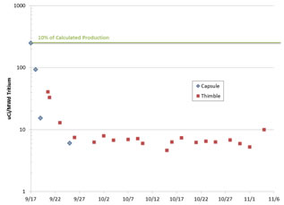
Fig. 5. Integrated tritium collected from the capsule and ICSA thimble exhaust gas. The final three points are taken during and after reactor shutdown but are adjusted for the equivalent time at 5.5 MW for direct comparison with the other data points.
model. 10% of this production rate is indicated by the line in Figure 5, aligning with the first measurement of tritium release from the capsule.
Although both capsule and ICSA thimble tritium levels decreased rapidly over the first week of irradiation, the thimble gas tritium release rates were consistently higher, indicating that the tritium diffused easily through the nickel capsule wall. The outside wall of the nickel is calculated to be about 50°C colder than the thermocouple, or ~650°C. At these temperatures metals are highly permeable to hydrogen, so such an effect is not unexpected compared to the smaller surface area available for axial diffusion of tritium from the salt chambers into the capsule cover gas stream.9
Future post-irradiation examination of the capsule and the material coupons will attempt to assess the total activity of tritium contained in the flibe and various materials and obtain a tritium balance for the experiment. Experience from the MSRE indicates that tritium, especially TF, will be preferentially adsorbed onto graphite.5 The large amount of graphite in the MSRE therefore substantially reduced the amount of tritium released from the system. Tritium may also have been held up in the experiment gas sampling system due to adsorption on the tubing. This can be countered in future experiments by mixing hydrogen into the helium cover gas mixture, but this was not done in this initial irradiation test for simplicity, and to prevent altering the redox potential of the salt.
Investigation of the condition of the capsule gas space and gas lines will also potentially yield information concerning the cause of the gas line obstructions. Finally, the flibe and material coupons will be used to assess corrosion, transport of corrosion products, and other material interactions with the liquid flibe environment under irradiation.
After cleaning and approximately one year of decay, the specimens’ activities were measured with an ion chamber and a germanium spectrometer. The SiC specimens had a surface dose rate of ~10 mR/hr; this was primarily β-activity and therefore likely due to 14C. The SS316 and Hastelloy specimens were approximately 100 mR/hr at 30 cm with contributions from 54Mn, 58Co, and 60Co. These isotopes are all expected activation products based on the composition of each specimen.
The final specimen weights are given in Table 3 along with the calculated mass loss. It should be noted that the surface area for the SiC/SiC fiber composite specimens used the bulk geometric area, not accounting for roughness or porosity, and therefore is an overestimation of the material loss.
For the metallic specimens there are two apparent trends; first, the specimens exposed in a binary environment without graphite had less mass loss than those in the ternary environment. Second, in each environment the SS316 corrosion rate was higher than that of the Hastelloy N. The SiC specimens in general had lower mass loss than the metals with the exception of the HNLS composite. Again, the increased apparent mass loss of the composites may be due to their open porosity increasing the available surface area for salt interaction.
Optical examination of the specimens via macrophotography and scanning profilometry produced results that agreed qualitatively with the weight change measurements. As shown in Figures 6 and 7, the surface of the specimens from the un-lined chambers had increased roughness, indicating some acceleration of corrosion due to the presence of the graphite surface. This is significant because in a salt-cooled reactor with solid fuel there will be significant exposed surface areas of both graphite and metal in the primary system.
TABLE III
Specimen Mass Change after Irradiation
Specimen |
Mass Change (mg/cm2)
±0.01 |
N1 (Hastelloy, lined) |
-0.23 |
N5 (Hastelloy, lined) |
-0.28 |
N2 (Hastelloy, unlined) |
-0.41 |
N6 (Hastelloy, unlined) |
-0.42 |
S1 (SS316, lined) |
-0.48 |
S5 (SS316, lined) |
-0.54 |
S2 (SS316, unlined) |
-2.09 |
S6 (SS316, unlined) |
-2.08 |
CVD SiC 1 |
-0.10 |
CVD SiC 2 |
-0.09 |
SA3 SiC/SiC |
-0.18 |
HNLS SiC/SiC |
-1.23 |
The TRISO particles were found to have cracking in their outer pyrolytic carbon layer (OPyC) that was not observed in surveys of the as-received particles, or in preliminary results from the autoclave tests at UW. Additional testing of repeated freeze-thaw cycles of TRISO particles in flibe found that previously-irradiated particles were much more susceptible to OPyC cracking than un-irradiated particles, however additional testing on larger batch sizes is required to definitively conclude that the irradiation sensitized the TRISOs to damage.
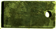
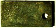
Fig. 6. Photographs of SS316 specimens after irradiation for lined (upper) and un-line (lower) chambers.
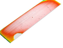
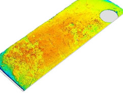
Fig. 7. Optical profilometry of the surface of irradiated SS316 specimens from lined (upper) and un-lined (lower) chambers.
VI. CONCLUSIONS
A capsule containing fluorine-lithium-beryllium salt and a variety of material specimens was successfully irradiated in the core of the MIT Research Reactor for 1000 hours at 700°C. This irradiation marks the first demonstration of flibe irradiation capability at the MITR and the first irradiation experiment of the Fluoride Salt High-Temperature Reactor IRP.
Gas samples collected from the space above the flibe chambers and from around the sealed experiment capsule identified a steady release of tritium that is estimated to be only a few percent of the total tritium produced. Post-irradiation examinations will attempt to identify if the tritium balance can be accounted for by tritium absorption in the salt, the specimens, and the capsule’s structural materials.
These initial results provide evidence of the high potential mobility of tritium in an FHR system consisting primarily of liquid flibe, graphite, and high-nickel alloys at high temperature. At the same time, a large percentage of the tritium that was predicted to have been generated in the salt was not detected in the gas phase, mirroring experience from the MSRE and indicating a potential for tritium control through tritium capture in solid components.
The data collected from this irradiation is immediately applicable to plans for future flibe irradiation experiments. In particular, there is increased confidence in the modeling and thermal control of the capsule with liquid flibe. In contrast, the gas handling system will need to be redesigned to prevent clogging of the gas sampling lines. Additionally, minimization of gas volumes must be balanced with personnel dose considerations due to the high activity and mobility of flibe activation products at any temperature. Future work on understanding tritium partitioning and the differences between nickel alloys and SS316 will help inform the evolution of the FHR conceptual design.
Acknowledgments
Financial support for this work is provided by the U.S. Department of Energy through an Integrated Research Project grant. We would like to acknowledge the help of our colleagues at the MIT: Dr. Kaichao Sun, Dr. Charles Forsberg, John Stempien, Chris Haid, and the NRL staff; at UW: Dr. Mark Anderson, Dr. Guoping Cao, Brian Kelleher, and Guiqiu Zheng.
References
1 C. FORSBERG, et. al., “Fluoride-Salt-Cooled High-Temperature Reactors (FHRs) for Base-Load and Peak
Electricity, Grid Stabilization, and Process Heat,” MIT-ANP-147, Massachusetts Institute of Technology (2013).
-
P.N. HAUBENREICH and J.R. ENGEL, “Experience with the Molten-Salt Reactor Experiment,” Nuclear Applications & Technology, 8, 118 (1970).
-
C. FORSBERG, “Fuel Geometry Options for Salt-Cooled Advanced High-Temperature Reactors,” Proceedings of ICAPP, Nice, France, May 13-18 (2007).
-
S.J. KIM, Y. OSTROVSKY, L.W. HU, G. KOHSE, "Thermal Analysis of High Temperature Irradiation Modules in In-Core Sample Assembly," Proceedings of the ANS Annual Meeting, San Diego, June 13-17 (2010).
-
R.E. THOMA, “Chemical Aspects of MSRE Operations,” ORNL-TM-4658, Oak Ridge National Laboratory (1971).
-
A.L. MATHEWS and C.F. BAES, “Oxide Chemistry and Thermodynamics of Molten Lithium Fluoride-Beryllium Fluoride by Equilibration with Gaseous Water-Hydrogen Fluoride Mixtures,” ORNL-TM-1129, Oak Ridge National Laboratory (1965).
-
C. FORSBERG, “2013 Annual Report: High-Temperature Salt-Cooled Reactor for Power and Process Heat,” NEUP 11-3272 Quarterly and Annual Report, October 20 (2013).
-
F.J. SMITH, L.M. FERRIS, and C.T. THOMPSON, “Liquid-Vapor Equilibria in LiF-BeF2 and LiF-BeF2-ThF4 Systems,” ORNL-4415 (1969).
-
A. SUZUKI, T. TERAI, and S. TANAKA, “Tritium Release Behavior from Li2BeF4 Molten Salt by Permeation Through Structural Materials,” Fusion Engineering and Design 51–52 (2000).
|