
Presented during the TopFuel 2015 conference
CORROSION AND HYDROGEN PICKUP IN ZIRCALOY-2 CHANNELS WITH AND WITHOUT PROXIMITY TO CONTROL BLADE
DAVID SCHRIRE
Vattenfall Nuclear Fuel
SE 162 87 Stockholm, Sweden
Tel: +46-76 809 6596, Email: david.schrire@vattenfall.com
KRISTINA KARLSSON
Forsmarks Kraftgrupp AB
SE 742 03 Östhammar, Sweden
Tel: +46-173 81293, Email: kka@forsmark.vattenfall.se
GÖRAN BLOMBERG
Studsvik Nuclear AB
SE 611 82 Nyköping, Sweden
Tel: +46- 155 221653, Email: goran.blomberg@studsvik.se
ANDREAS MOECKEL
AREVA GmbH
Paul-Gossen-Straße 100, 91052 Erlangen, Germany
Tel: +49-9131-900 95316, Email: andreas.moeckel@areva.com
ABSTRACT
The hydrogen pickup behaviour in BWR fuel channels is an important characteristic not least because the hydrogen is implicated in the irradiation growth behaviour which can lead to distortion. It has been observed that fuel channels with extensive control blade exposure (i.e. adjacent to a partially or fully inserted control blade for a significant amount of time) early in life tend to bow towards the control blade side late in life. Since bow is understood to result from a difference in growth between opposite sides of a channel, it can be assumed that the sides adjacent to a control blade early in life tend to grow more later in life. Another consequence of operation adjacent to a control blade is that the outer surface of the channel facing the control blade (or control blade handle) develops what is commonly known as “shadow corrosion”. Shadow corrosion occurs on Zr-base alloys in contact with or in close proximity to other metallic alloys in the reactor core radiation field in BWRs or other reactors with simi-larly oxidising water conditions.
Due to an issue with thermal fatigue of the control blade shafts, the Forsmark 3 plant operated for 7 months with all the control blades inserted 500 mm into the core. The bottom sections of fuel channels at all burnup levels were thus continuously adjacent to control blades during this time. Taking ad-vantage of this unique opportunity, at the end of this cycle it was decided to cut out samples from a 1-cycle and a 6-cycle Zircaloy-2 channel that both experienced this unusual control blade exposure without any significant prior control blade exposure, for post-irradiation hydrogen measurements and metallographic examination at the Studsvik hot cell laboratory.
The results of the post-irradiation examinations showed that:
-
The shadow corrosion rate was somewhat higher on the 6-cycle channel than on the 1-cycle channel.
-
For the 1-cycle channel the side adjacent to the control blade and the opposite side at the same elevation had the same low hydrogen concentration, showing that the early-in-life con-trol blade exposure did not cause any significant increase in hydrogen pickup.
-
For the 6-cycle channel the samples on the side adjacent to the control blade had far higher hydrogen concentrations than the opposite side at the same elevations. This difference was higher at the higher elevation samples than at the elevation directly adjacent to the control blade.
Since the 1-cycle sample from the side adjacent to the control blade had significant shadow corrosion on the outer surface but about the same low hydrogen content as the sample at the same elevation from the opposite side (without any shadow corrosion), it is concluded that the shadow corrosion from the proximity to the control blade per se did not make any significant contribution to the hydrogen pickup. For the 6-cycle channel there was a larger increase in the hydrogen concentration between the control blade side and the opposite side at higher elevations, well above the zone in direct proximi-ty to the control blade. Since this could not be due to shadow corrosion, it is concluded that the higher hydrogen pickup on the control blade side of the 6-cycle channel is probably due to some other effect of the different conditions on the two sides of the assembly, for instance the local power, fast neutron flux and void distribution.
1. Introduction
1.1. Background: impact of control blade exposure on channel behaviour
The hydrogen pickup behaviour in BWR fuel channels is an important characteristic not least because the hydrogen is implicated in the irradiation growth behaviour which can lead to distortion. It has been observed that fuel channels with extensive control blade exposure (i.e. adjacent to a partially or fully inserted control blade for a significant amount of time) early in life tend to bow towards the control blade side late in life [1]. Since bow is understood to result from a difference in growth between opposite sides of a channel, it can be assumed that the sides adjacent to a control blade early in life tend to grow more later in life. Another consequence of operation adjacent to a control blade is that the outer surface of the channel facing the control blade (or control blade handle) develops what is commonly known as “shadow corrosion”. Shadow corrosion occurs on Zr-base alloys in contact with or in close proximity to other metallic alloys in the reactor core radiation field in BWRs or other reactors with similarly oxidising water conditions.
1.2. Unique operating condition in Forsmark 3 cycle 24B
Vattenfall’s Swedish BWRs are normally operated such that medium burnup fuel assemblies (typically in their 3rd year of operation) are placed in control cells with extensive control blade exposure, while fresh and high burnup fuel have a minimum of control blade exposure during normal operation. However, due to an issue with thermal fatigue of the control blade extender shafts, the Forsmark 3 plant operated for seven months (cycle 24B) with all the control blades inserted 500 mm (14 %) into the core [2]. The lowest 500 mm of fuel channels at all burnup levels were thus continuously adjacent to control blades during this time.
Taking advantage of this unique opportunity, at the end of this cycle it was decided to examine samples from a 1-cycle and a 6-cycle Zircaloy-2 channel that both experienced this unusual control blade exposure without any significant prior control blade exposure.
2. Channel design and operating history
Both the fuel channels were from ATRIUMTM 10B fuel, with nominally identical channel design and material. The channels were fully recrystallized Zircaloy-2, with a constant wall thickness of 2.3 mm. In the Forsmark 3 lattice the channel-channel water gap is nominally 19.4 mm on the control blade sides and 12.9 mm on the opposite sides. Forsmark 3 operates with normal water chemistry (NWC), i.e. with no injection of hydrogen, zinc or noble metals.

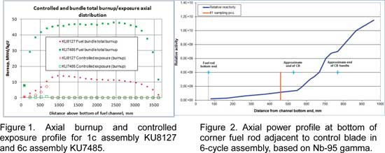
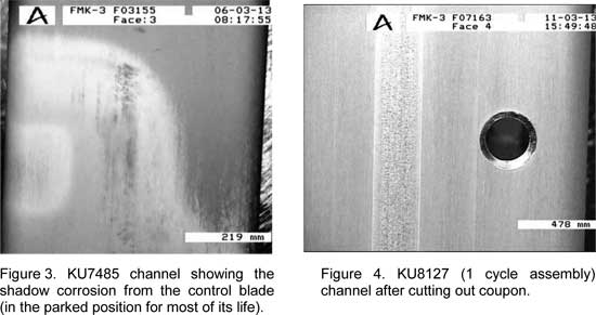
The assembly and channel overall operating history is summarised in Table 1. The node-wise axial burnup distributions of the 1-cycle fuel bundle KU8127 and 6-cycle fuel bundle KU7485 are shown in Figure 1 together with the equivalent controlled exposures for each node. The nodal controlled exposure is the cumulative burnup for the node for that time in which the control blade (or its handle) has been inserted into that node. This metric is equally weighted irrespective of when in life the control blade has been present in the node. As can be seen in Figure 1, for both assemblies/channels there was zero control blade exposure above the lowest 5 nodes at any time in the fuel lifetime. In the lowermost node (node 1) the controlled exposure is equal to the total burnup in that node – this is because with the control blade fully withdrawn (parked position) the control blade handle extends into the first node, so irrespective of the control blade position this node experiences “control”. The shadow corrosion formed from proximity to the control blade handle in the withdrawn position is clearly seen in the lower part of the 6c channel (Figure 3). For the 1c assembly KU8127 the controlled exposure in nodes 2-5 is almost as much as the total burnup, since those nodes only experienced about 70 days of uncontrolled operation prior to the partial blade insertion. For the 6c assembly KU7485 the controlled exposure in nodes 2-5 is much lower than for the 1c assembly since this assembly operated at a much lower power during cycle 24B (it had a higher burnup and was on the core periphery), and represents only a very small fraction of the total burnup for these nodes, see Table 2. It should be noted that the 6c assembly KU7485 was located on the core periphery for its last 3 cycles, so the control blade corner faced inwards. The assembly achieved a burnup of 35.2 MWd/kgU during its first 3 cycles, but only an additional 5.9 MWd/kgU in its last 3 cycles on the periphery. Nonetheless, the fuel rods at both sides of the assembly (adjacent to the channel sampling positions) had similar end of life burnups and so the channel fast neutron fluences were probably relatively similar on both sides during the first 3 cycles and only differed much in the last 3 cycles.
Figure 2 shows the axial power profile in the lower part of the corner fuel rod adjacent to the control blade corner (a1 rod) during the last cycle of operation, based on Nb-95 gamma spectrometry. The effect of the partially inserted control blade, as well as the control blade handle, are clearly seen.

3. Poolside inspection and sampling
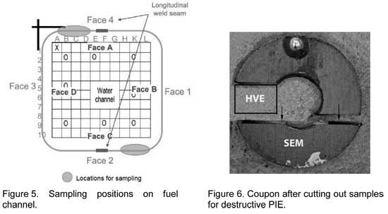
Circular samples (coupons) were cut from the CB (Control Blade) side (Face 4) and the non- CB side (Face 2) beside the longitudinal weld seam, see Figures 4 and 5 below. On each side, coupons were cut at three axial positions: 460 mm, 1930 mm and 3290 mm above the bottom of the channel. A new replacement channel was obtained for the continued operation of the 1-cycle bundle, since its original channel had to be scrapped after the coupons had been cut out.
The coupons were positioned by drilling a pilot hole through the channel wall, marking the upper end with the pilot drill, and then cutting out the coupons with a core drill, see Figure 6 below.
Channel bow measurements were performed on both channels before the sample cutting. The maximum bow was as follows, where a negative value is away from the CB.
KU8127 (1 cycle) x-direction -0.35 mm y-direction -0.46 mm
KU7485 (6 cycle) x-direction +0.98 mm y-direction +2.26 mm
4. Hot Cell Post-Irradiation Examination (PIE)
4.1. Experimental methods
The channel coupons were retrieved from the shipping container, and photographed to rec-ord the inner and outer surface appearance. Hot vacuum extraction (HVE) and scanning electron microscopy (SEM) samples were cut out as shown in Figure 6.
The hydrogen content was measured by HVE using an ELTRA OH-900 Hydrogen Determina-tor as follows: The samples (weighing about 0.1 g) were placed in a graphite crucible and heated up to about 2000 °C with argon as carrier gas. Any CO that might be present was removed by passing the gas mixture through Schütze’s reagent (I2O5) to oxidize the CO to CO2 which was subsequently removed by chemical reaction with NaOH. The gas mixture of argon and hydrogen then passed through a thermal conductivity detector with low drift, high resolution and wide measuring range. The hydrogen concentration was determined by an integrator. Before the measurements, the HVE equipment was calibrated using certified Ti-based standards with 62.5 ± 3.2 ppm hydrogen content. Although the absolute accuracy of the hydrogen determination using HVE is no better than the relative accuracy of the calibra-tion standards (in this case about 5 %), the reproducibility/precision has previously been found to be better than this, except at very low concentrations. The measurements were per-formed on samples which included any attached oxide, so the reported hydrogen concentrations refer to the total evolved hydrogen relative to the total sample weight.
Cross-sectional arcs were cut out for scanning electron microscopy (SEM), where the inner and outer surface could be examined along a plane just above the word “SEM” in Figure 6. The samples were embedded in epoxy resin, ground and polished with 0.04 μm colloidal SiO2 suspension as a final oxide polishing step. The examinations were performed in a JEOL 6300 SEM. Micrographs were taken in BEI-mode (Backscatter Electron Imaging) using dif-ferent instrument settings for optimised imaging of the oxide or the hydrides. The oxide thickness was evaluated from the micrographs acquired in the SEM. The average thickness was determined by measuring the total oxide area in each micrograph using a Leica QWin image analysis software. The oxide area was divided by the width of the measured oxide layer in each micrograph to obtain the average oxide thickness. This method takes into ac-count variations in oxide thickness and delamination or separation of oxide layers.
4.2. Results
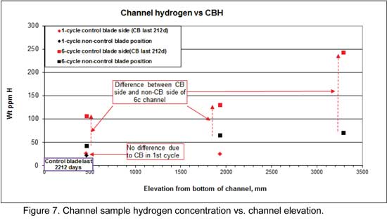
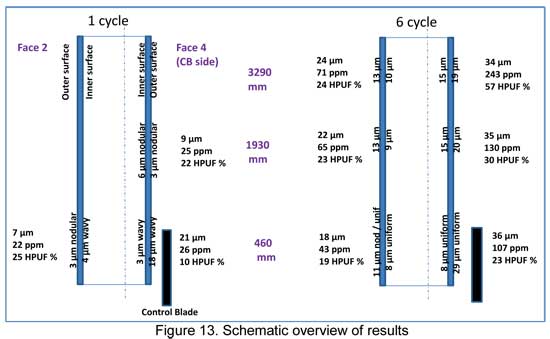
The hydrogen concentrations measured by HVE are shown in Figure 7. The red symbols represent the measurements on the control blade side (face 4 in Figure 5) and the black symbols represent the measurements on the non-control blade side (face 2 in Figure 5). The 1-cycle channel (diamond-shaped symbols in Figure 7) had a low concentration of just over 20 ppm for both the CB side (face 4 in Figure 5) and the non-CB side (face 2 in Figure 5) at the lowest elevation (460 mm above the bottom of the channel). At this elevation the control blade was adjacent to the CB side during cycle 24B. At the mid-height elevation (1930 mm) the hydrogen was only measured on the CB side and was essentially the same as at the lower elevation.
The 6-cycle channel (square symbols in Figure 7) had very much higher hydrogen levels in all the samples measured. On the non-CB side, the hydrogen concentration increased with elevation from just over 40 ppm at the lowest position to just over 70 ppm at the top sample. On the CB side, the hydrogen concentration was very much higher, increasing with elevation from just over 100 ppm at the lowest position to just over 240 ppm at the top sample.
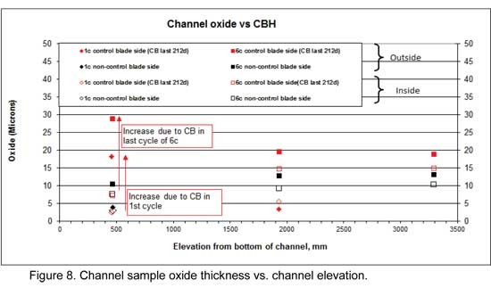
The average oxide thicknesses measured in the SEM are shown in Figure 8. The red sym-bols represent the measurements on the control blade side (face 4 in Figure 5) and the black symbols represent the measurements on the non-control blade side (face 2 in Figure 5). The filled symbols are the oxide thickness on the outside of the channel wall and the open sym-bols are the oxide thickness on the inner surface. The oxide layer appearance (topography) varied between the samples and frequently between the inner and outer surface of the same coupon. The oxide appearance is described qualitatively below.
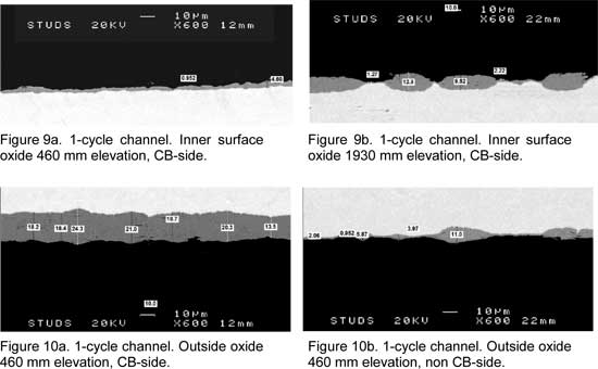
1-cycle channel. The inner oxide layer was rather uniform in both the 1-cycle samples at the lowest elevation but thicker nodules were present at the 1930 mm elevation (Figures 9a and 9b). The outer surface oxide layer was much thicker, and relatively uniform, in the sample that had been adjacent to the control blade (460 mm elevation on CB-side), compared to the other samples (Figures 10a and 10b).
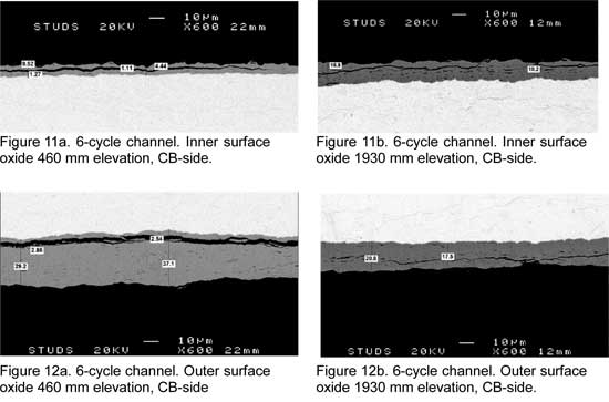
6-cycle channel. The inner oxide layer was rather even in the 6-cycle samples (Figures 11a and 11b). The average thickness was the same on both sides at the 460 mm elevation, and thicker higher up. The outer surface oxide layer was thicker in the sample that had been ad-jacent to the control blade (460 mm elevation on CB-side), compared to the other samples. (Figures 12a and 12b). Both the inner surface and outer surface oxide showed some appar-ent tendency to delamination (cracks) which was not seen in the 1-cycle samples.
5. Discussion
The oxide appearance has been broken down into the following rough categories, and the different sample surfaces are characterized accordingly in Table 3:
-
“Wavy” where there is a continuous oxide coverage, but the thickness varies signifi-cantly with a wavy appearance, see e.g. Figure 9a.
-
“Nodular” ” where the individual nodules are about an order of magnitude thicker than the thin oxide separating them, see e.g. Figures 9b and 10b.
-
“Uniform” where the thickness varies less than about a factor 2, irrespective of the ac-tual thickness or condition of the layer, see e.g. Figures 11b and 12b.
It is considered likely that the wavy or nodular oxide appearance seen in the 1-cycle channel would eventually progress to the continuous oxide film categorised as “uniform”.
Shadow corrosion. The shadow oxide thickness (oxide attributable to the shadow corrosion) can be estimated from the difference in oxide thickness between the CB-side outer surface at the 460 mm elevation, compared to the non-CB side at the same elevation. The shadow cor-rosion can also be estimated from the difference in oxide thickness between the outer surface (facing the control blade) and the inner surface, at the 460 mm elevation. In both cases for the 1-cycle channel, this results in an apparent shadow corrosion during cycle 24B of about 15 µm, as indicated in Figure 8. For the 6-cycle channel, the shadow oxide thick-ness estimated in the same way results in an apparent shadow corrosion during cycle 24B of 18-22 µm, as indicated in Figure 8. It thus seems that the 212 days of exposure to the partial-ly inserted control blade resulted in a somewhat thicker shadow corrosion on the 6-cycle channel than on the 1-cycle channel, despite the fact that the latter had only operated for 70 days prior to the control blade exposure and thus not built up a thick oxide layer prior to the control blade exposure.
This observation is notable when bearing in mind the fact that the 6-cycle channel operated in a far lower radiation field during cycle 24B when the shadow corrosion occurred. Although not a perfect measure of the radiation field, the difference in “controlled exposure” (fuel bun-dle nodal burnup accumulation while adjacent to the control blade) gives some indication of this difference between the two channels. In the controlled node 3 (corresponding to the 460 mm elevation coupons) this parameter was almost an order of magnitude lower for the 6-cycle assembly than for the 1-cycle assembly. Since shadow corrosion is believed to be a form of radiation assisted galvanic corrosion [3], if the radiation field intensity plays a role it might have been expected that the shadow corrosion should have been equal or greater in the 1-cycle channel. However, the exact distance between the control blade surface and the channel might vary slightly from case to case, which could potentially explain the faster shadow corrosion in the 6-cycle channel.
General corrosion. The corrosion on all the sample surfaces from the 1-cycle channel, apart from the surface exposed to the control blade with shadow corrosion, had average oxide thicknesses ranging from just under 3 µm to just over 5 µm at both the 460 mm and the 1930 mm elevation (Figure 8). For the 6-cycle channel, however, there was a more noticea-ble (factor 2) increase in the general oxide thickness from the 460 mm to the 1930 mm elevation (Figure 8). At the 1930 mm elevation both the inner and outer surfaces of the 1-cycle channel had characteristically nodular oxide appearance, see Figure 9b and Table 3. The oxide on the 6-cycle channel at the same elevation had a more uniform appearance, see Figure 11b and 12b. Assuming that the 6-cycle channel had a similar oxide layer at the end of its first cycle to the 1-cycle channel then the subsequent growth of the oxide in the later cycles primarily consisted of “filling in” the oxide layer between the nodules, rather than a further increase in the depth of the nodules.
Hydrogen pickup. The measured hydrogen content in three coupons from the 1-cycle channel all showed low and similar levels of 22-26 ppm, despite the 3-times thicker total ox-ide thickness (inner and outer surface) for the 460 mm sample exposed to the control blade, see Figure 7. There was thus no indication of any additional hydrogen pickup due to shadow corrosion in these channel samples. The 6-cycle channel sample exposed to the control blade, however, had a far higher hydrogen content than the sample from the opposite side at the same elevation, see Figure 7. The difference between the control blade side (face 4) and the opposite side (face 2) was even more striking for the two higher elevations. Since the higher elevations were never exposed to control blade presence, the higher hydrogen level in face 4 cannot be explained by shadow corrosion due to control blade proximity, which has been claimed in other cases [1, 4, 5]. The apparent “hydrogen pickup fraction” for the sample positions where both hydrogen concentration and inner and outer surface average oxide thickness were measured, is shown in Table 3, assuming the oxide has 100% theoretical density.
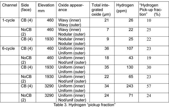
As explained above, it would seem that the shadow corrosion (estimated to be about 15 µm for the 1-cycle channel) did not result in significant hydrogen pickup. Similarly, for the 6-cycle channel, the total hydrogen content in the CB side at 460 mm elevation (which experienced control blade proximity and shadow corrosion) is lower than for the higher elevations on the same side. So what could have caused the higher total hydrogen pickup (and apparent pickup fraction) on the CB side of the 6-cycle assembly compared to the opposite side?
One difference between the two channel sides is that the channel-channel water gap is larg-er on the CB-side (see section 2 above). However, it is not evident that this would affect the hydrogen pickup, since the non-boiling bypass water was about the same temperature on both sides when the assembly operated in more central positions in the core in the first three cycles. Instead, it is more likely that the last 3 cycles when the assembly was in the same core position on the periphery may have had some effect.
The entire assembly had a very low average void in the last three cycles (exit void of about 25 %), with no bulk boiling calculated for the lowest 13 nodes including the 1930 mm eleva-tion, so presumably what void there was occurred mainly on the side facing the core centre (towards the CB sides). The inlet temperature was 275-277 ºC, and since there was no bulk boiling in the bypass the exit temperature on both sides was below 286 ºC. Since the bypass flow area is larger, and the heat flux lower, on the outer facing surface the bypass water tem-perature (and thus channel temperature) was somewhat lower compared to the inboard-facing sides. However, it does not seem likely that the slightly higher bypass water tempera-ture on the CB-side than the opposite side could explain the difference in hydrogen pickup, since the hydrogen content at both the 460 mm and 1930 mm levels on the CB-side were higher than the hydrogen content in the opposite side at higher elevations (where the chan-nel temperature would also have been higher).
The non-CB side had a lower fast neutron fluence than the CB-side during the last three cy-cles, which may provide an explanation for the difference in behaviour. It is possible that although both sides of the channel had experienced substantial irradiation damage during the first three cycles of operation, the outer-facing sides experienced insufficient fast neutron flux in the last three cycles to undergo the rapid increase in hydrogen uptake that is typical for irradiated Zircaloy-2 in in-pile BWR conditions after high exposure.
Neither channel had appreciable bow. The 1 cycle channel had a very small negative bow (i.e. away from the CB corner), remaining from the as-fabricated condition (Forsmark 3 channels are oriented such that any existing bow is away from the control blade). The 6 cycle channel has a small bow towards the CB sides, which is not surprising considering the higher neutron fluence and hydrogen content on those sides.
6. Conclusions
The results of the post-irradiation examinations showed that:
-
The shadow corrosion rate was somewhat higher on the 6-cycle channel than on the 1-cycle channel.
-
For the 1-cycle channel the side adjacent to the control blade and the opposite side at the same elevation had essentially the same low hydrogen concentration, showing that the early-in-life control blade exposure did not cause any significant increase in hydrogen pickup.
-
For the 6-cycle channel the samples on the side adjacent to the control blade had far higher hydrogen concentrations than the opposite side at the same elevations. This difference was higher at the higher elevation samples than at the elevation directly adjacent to the control blade.
-
Since the 1-cycle sample from the side adjacent to the control blade had significant shadow corrosion on the outer surface but about the same low hydrogen content as the sample at the same elevation from the opposite side (without any shadow corro-sion), it is concluded that the shadow corrosion from the proximity to the control blade per se does not make any significant contribution to the hydrogen pickup.
-
For the 6-cycle channel there was a larger increase in the hydrogen concentration be-tween the control blade side and the opposite side at higher elevations, well above the zone in direct proximity to the control blade. Since the difference at the higher el-evations could not be due to shadow corrosion, it is concluded that the higher hydrogen pickup on the control blade side of the 6-cycle channel is probably related to thicker oxide and is due to some other effect of the different conditions on the two sides of the assembly, for instance the local power, fast neutron flux and void distribu-tion.
Acknowledgements
The authors are grateful to Jesper Kierkegaard for assistance in selecting the candidate channels and insights into relevant aspects of their operation.
References
-
“Shadow Corrosion Resulting in Fuel Channel Bowing”. USNRC Information Notice 89-69 Supplement 1, 25 August 2003.
-
Operating Experience from Swedish Nuclear Power Plants 2008. Kärnkraftsäkerhet och Utbildning AB, 2009.
-
G Lysell, A-C Nystrand and M Ullberg, “Shadow Corrosion Mechanism of Zircaloy”, ASTM STP 1467, 2005.
-
S. T. Mahmood et al., “Channel Bow in Boiling Water Reactors – Hot Cell Examination Results and Correlation to Measured Bow”, Proc. Int. LWR Fuel Performance Meeting San Francisco, California, Sept. 30 – Oct. 3, 2007.
-
S. T. Mahmood et al., “Shadow Corrosion-Induced Bow of Zircaloy-2 Channels”. 16th Int. Symposium on Zirconium in the Nuclear Industry, 13 May, 2010, Chengdu, China.
|

