

European
Nuclear Society
e-news
issue 49: November 2015
Dear Reader,
As the new editor-in-chief, I would like to welcome you to the ENS News publication. Over the past ten years, Mr. Mark O’Donovan took great care to bring you a high-quality publication with relevant and interesting content. Now that he has decided to retire, it is up to me to strive and keep the quality of ENS News up to Mark’s standards.
The second half of 2015 was marked by numerous events spanning all fields of nuclear energy and nuclear research. Most importantly, all events in the nuclear industry are being focused on the up-coming UNFCCC COP21 climate change conference which will take place in December 2015 in Paris. The conference will bring together 196 nations who will have to hammer out a deal to reduce greenhouse gas emissions and agree to limit the effects of climate change. We all know the target of keeping the temperature increase to 2 degrees C by the end of the century.
The nuclear industry has a big stake in climate change mitigation politics, policies and scenarios. Environmentally, nuclear is a low-carbon source of energy and can help avoid CO2 emissions while providing a constant, large-scale power supply. It is indicative that the Intergovernmental Panel on Climate Change, the body which conducts peer-reviews on the science behind climate change, shows only eight out of more than a thousand scenarios which include a nuclear-free way of tackling climate change.
Economically, nuclear is very similar to renewable energy sources. Both have a high up-front cost but a very low marginal or operational cost. This means that both nuclear and renewable energy sources cost a lot of money to build but very little to maintain. At the moment, the increased use of renewables has pushed wholesale market prices down (because they cost very little to operate) but consumer prices have gone up (due to subsidies for the up-front costs). This situation is unsustainable for two reasons – utilities are not receiving enough money to cover their operational costs for other electricity generation technologies and consumers are paying every higher prices.
One country in Europe to have realised the issues brought in by subsidising renewables is the United Kingdom. After the landslide election victory of the Conservative party, Mr David Cameron has decided to cut subsidies to renewable energy installations. Then, in October, the UK government announced a deal with its Chinese counterparts that 33.5% of the Hinkley Point C nuclear power station will be paid for by Chinese investors. In addition, China will take a large stake in Sizewell B and perhaps even see a Chinese reactor being built at Bradwell. These plans for building four EPR reactors and one Chinese reactor, together with the three Westinghouse AP1000 reactors planned for Moorside and the Hitachi GE ABWR planned for Wylfa, will bring online nine new reactors with a total power output of around 11 GW.
The UK’s push for a nuclear new build programme comes in the context of the EU’s pilot project for building an Energy Union. EU Commissioner Maroš Šefčovič’s plans for interconnecting and decarbonising Europe through sustainable and competitive energy technologies will require a lot of work and a completely new energy market design. To this end, the EC opened a public consultation on the topic. The main challenges to be addressed are related to ensuring affordable consumer prices for electricity while not condemning utilities to a life of selling their production at below-cost levels.
The economics of electricity markets will play an important role in the COP21 negotiations when ministers try to hammer out a deal to save the planet from overheating. Let us hope that the benefits of using nuclear energy, which is more like renewables than many are ready to acknowledge, will be taken into account once decision-time comes around.
Lubomir Mitev
Editor-in-Chief, ENS NEWS
http://www.euronuclear.org/e-news/e-news-49/presidents-contribution.htm


|
On June 22nd, I attended the joint ENS-SFEN Young Generation Forum in Paris. All our readers know the importance of the young generation in our 23 member societies: they are the future of nuclear energy in Europe and beyond. The forum was held in “la Cité des Sciences et de l’Industrie” at La Villette, in the northern part of Paris. It was a special privilege for me to open the event as ENS President, all the more since I grew up in the vicinity of La Villette in the mid fifties, when la “Cité des Sciences” was still thirty years ahead. But let me quote my own words: |
“Distinguished delegates, Ladies and Gentlemen,
It is customary to begin such a speech by thanking the organizers, Sophie Missirian at SFEN and Eileen RADDE at ENS, both chair ladies of the young generation networks for inviting the first speaker. This, I will not fail to do. But my reasons will be somewhat non conventional.
The first reason is both related to youth (you in the audience), and to my own life. Indeed, I grew up less than a mile away from this very spot in La Cité des Sciences at la Villette. It was in the mid fifties and the early sixties. This was still an immigration suburb where butchery was practiced at a large scale, maybe you will have time to take a look at the transformed XIXth century buildings during the 3 days of the conference: Avenue du Charolais and la Grande Halle, only a 15 minute walk from this building. In those days, the Paris circular highway did not exist, it was under early construction stage. France was evolving rapidly from its post war colonial empire. Of course the internet was 40 to 50 years away, even conventional copper wire telephones were quite scarce for the ordinary Frenchman or woman.
Nuclear did exist however first for military applications since our great political leader of the time wanted independence from the Americans. They had nearly pushed him into political oblivion during the Second World War and he could not trust them completely in all nuclear matters as the English leaders would do, on the other side of the channel.
On the civilian side, generation one small power reactors were commissioned with natural uranium as fuel and graphite as moderator. Later, in the late seventies we switched to what was at the time a leading American technology: the Pressurised Water Reactors (PWR’s) of the Westinghouse design. It is now forgotten that it took us some time in France, De Gaulle had already left power when it happened and we were quite successful. In a very short period of time we built 54 Westinghouse licensed reactors and 4 on our own with Framatome. Most of you know them under the name of Generation 2 reactors and we plan to extend their lifetime up to 60 years, which would bring the most recent units the N4 at Civaux and Chooz well beyond 2050. Of course we were not alone in Europe to deploy nuclear power for electricity generation. Western and northern countries did the same not only with gas graphite reactors (the British), with PWR’s but also with Boiling Water Reactors, the BWR’s. Central and Eastern Europe (and also Finland at Loviisa) adopted Russian designs, the VVER’s which in Russian means something similar to Pressurized Water Reactors. There were also a limited number of graphite reactors, the RBMK’s now shut down, Ignalinia in Lithuania and Candu technology with heavy water in Romania, to the East on the Cernavoda site.
But this is the past, and one cannot live only by looking in the mirror at past history all the more when speaking to an audience of young people, the young generation of 23 nuclear societies all around Europe. The present is both a divided Europe, evenly split into 2 halves about nuclear energy and a massive energy transformation underway because of climate change. It is quite relevant that you and the organizers have chosen the theme of climate change and nuclear as a key part of the solution in the fight against those problems for your bi annual gathering. Let me comment that the energy transformation has its own name in the different European countries and that it is led and pursued according to the political cultures of the 28 Member States. To speak first of the major countries, Die Energie Wende in Germany was decided by the political leadership, Kanzlerin Merkel in a few weeks in 2011. In my own country France, the new law Transition Energétique pour la Croissance Verte, the first part of which can be translated as Energy Transition took months and months of debate, I would say a good 2 years. It is not yet in force, even though the legislative process is nearing completion1. In Europe the Commission has both to lead the climate change energy transformation and to respect the founding treaties which recognize energy choices as a fundamental right and prerogative of each of the 28 Member States. This is why it has come up with the concept of energy union and its main objectives all climate change compatible, with low carbon technologies and energy sources, with a sophisticated governance mechanism and with European wide debates about market design. Let me point out that nuclear is present in the wider European energy debate, through its European Nuclear Energy Forum a high level meeting of ministers, company CEO’s, high level representatives of the civil society, Directors General of main European associations. Its last plenary was held in Praha, Czech Republic at the end of May. The Czech Energy Minister Mr. Mladek concluded among other things that Nuclear Energy has its place in the European Union Energy Portfolio and that a market design favorable for nuclear investment has not yet been achieved. It needs further work which I hope is underway in Europe and at the Commission.
There is another upcoming political event at the end of this year in Paris : the twenty first Conference of Parties which you know under its acronym: COP 21. It is established under a United Nations Framework to fight Climate Change and it is the precise meaning of another acronym, UNFCC. It is important because of the urgency to act and because past COP gatherings have not achieved sufficient commitments from the Green House Gas emitting countries to reduce emissions and reach what experts consider as a tolerable level, synthetized in the 2°C scenario. One of today’s speakers, Madame Masson Delmotte will give you more information about that. It is hoped but it is only a hope at the present stage of negotiations that more substantial commitments will be reached this year getting our future planet on a safer course. Reaching some kind of agreement between 196 countries, the parties to the United Nations Framework is not an easy task. It is mostly a task for the Parties themselves, their political leaders and the technical negotiators they have designated. However, all of us in this room Young or not so Young have a part to play, even if we are several levels below the negotiators.
For nearly 30 years your elders (and that includes me) have been convinced that nuclear is a low carbon technology, that it does note emit CO2 when generating nuclear heat even though carbon dioxide is emitted when the materials to build a nuclear plant are fabricated (steel, concrete, other alloys, fuel oxides and so forth). Therefore, yes we believe that nuclear is a key part of the solution to climate change problems. Have we been good at convincing others ? Well honestly, we the elders think not so much :
The community of climate change experts and negociators which is a wide and respected community coined a sentence, a saying at a previous conference
“DO NOT NUKE THE CLIMATE”
And it was not only a saying, it had financial implications, important ones.
This is why we, the elders and their nuclear industry need you the young generation of the European nuclear societies to better formulate the message with all the tools your generation can muster : the web, the social networks, instant image, photographs and video projections using the afore media….. And of course and above all, we need your personal conviction.
Technicalities of why nuclear is part of the solution, a key part, I would say, I will leave to my distinguished friend and colleague, CEA Nuclear Energy Director Christophe BEHAR. He is due to speak this afternoon, just after lunch.
I can see in your program that you will be covering many important subjects concerning nuclear energy in the next 3 days : nuclear waste, geological disposal in the northern countries and societal impact tomorrow, changing electricity markets and the role of nuclear energy in the change on Wednesday and Generation IV Reactors and closed fuel cycle, that should also be on Wednesday.
They are all important to shape the future of nuclear energy, the future that belongs to you, the Young Generation of the European Nuclear Societies.”
1The speech was delivered on June 22. The energy transition law was voted by the French Parliament a month later, at the end of July 2015.
http://www.euronuclear.org/e-news/e-news-49/ygn-report.htm
The reactor fuel performance conference TopFuel 2015 takes place every third year in Europe and is organized by the European Nuclear Society (ENS). When the conference is not in Europe, the American Nuclear Society and the Atomic Energy Society of Japan, together with the Chinese Nuclear Society and the Korean Nuclear Society, host the event in their respective continent.
After the European conferences in Paris, France, in 2009 and in Manchester, UK, in 2012, the nuclear fuel community met in Zürich, Switzerland in September 2015. As usual the TopFuel conference represented a great opportunity to meet the whole nuclear fuel community. The participants include operators, vendors, nuclear regulatory authorities, technical support organisations (TSO), research institutes and universities worldwide. At the same time, several PhD students and postdoc researchers used the change to present their own results and to come and keep in touch with the nuclear fuel community.

The TopFuel 2015 conference was opened by the chair, Dr. Marco Streit (Paul Scherrer Institute, President of Swiss Nuclear Society) and the programme committee chair Johannes Bertsch (Paul Scherrer Institute). The openning session included a panel discussion under the title Upcoming Challenges Of The Fuel Market and was moderated by Tony Williams (Axpo Power AG, Switzerland). The fuel vendors GNF, Westinghouse, AREVA, ENUSA and Rosatom announced a 40% overcapacity in fuel assembly production in Europe. Several reasons exist for this, e.g. the immediate shutdown of several nuclear power plants in Germany after the 2011 accident at the Fukushima nuclear power plant. In general, several vendors expect a consolidation and / or collaborations in the European fuel market in the future. The openning session was completed by an overview of the activities of the OECD/NEA Expert Group on Accident Tolerant Fuels for Light Water Reactors, focussing on fundamental properties and behavior under normal operation and accident conditions.
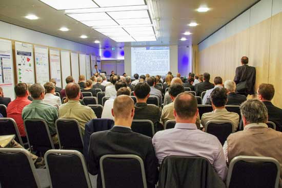
After the opening session the participants had the choice between several parallel technical sessions. The sessions highlighted new trends, experiences, developments and R&D results in the fields of operation, operational transients, design basis accidents (incl. LOCA) and their modelling / simulation with computer codes. For example, new experimental results were presented by JRC-ITU (European Commission) regarding micro-hardness and local properties of high burnup UO2 fuel. In spite of the increase of the fuel burn-up in many commercial reactors worldwide there is still R&D needed to understand and characterize in detail the processes ongoing in the high burnup structure occurring in the fuel pellet periphery.
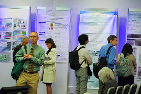
Beside these topics the development of accident tolerant fuels was given attention in three sessions of the conference. As is well known, this topic has increased in interest in the last years. It seems that these developments are challenging for all involved parties. Nevertheless, Westinghouse pointed out that the first test with accident tolerant fuel in a commercial reactor was planned for 2022.
In addition, the wide spectrum of topics in the conference program was completed by two sessions about investigation of fuel for fast Gen-IV reactors (ASGARD) and three sessions about spent fuel.
After three days of interesting and great presentations, lectures, discussions and get-together of the fuel community the conference participants could take the opportunity to attend a technical tour. They could choose between a visit of the hot labs of the Paul Scherrer Institute (PSI), of the nuclear power plant Gösgen, or to go to Mont Terri Rock Laboratory for nuclear waste repository research all located in Switzerland.
TopFuel 2016 will take place in Idaho, USA, in 2016.
http://www.euronuclear.org/e-news/e-news-49/corrosion-and hydrogen.htm

Presented during the TopFuel 2015 conference
DAVID SCHRIRE
Vattenfall Nuclear Fuel
SE 162 87 Stockholm, Sweden
Tel: +46-76 809 6596, Email: david.schrire@vattenfall.com
KRISTINA KARLSSON
Forsmarks Kraftgrupp AB
SE 742 03 Östhammar, Sweden
Tel: +46-173 81293, Email: kka@forsmark.vattenfall.se
GÖRAN BLOMBERG
Studsvik Nuclear AB
SE 611 82 Nyköping, Sweden
Tel: +46- 155 221653, Email: goran.blomberg@studsvik.se
ANDREAS MOECKEL
AREVA GmbH
Paul-Gossen-Straße 100, 91052 Erlangen, Germany
Tel: +49-9131-900 95316, Email: andreas.moeckel@areva.com
The hydrogen pickup behaviour in BWR fuel channels is an important characteristic not least because the hydrogen is implicated in the irradiation growth behaviour which can lead to distortion. It has been observed that fuel channels with extensive control blade exposure (i.e. adjacent to a partially or fully inserted control blade for a significant amount of time) early in life tend to bow towards the control blade side late in life. Since bow is understood to result from a difference in growth between opposite sides of a channel, it can be assumed that the sides adjacent to a control blade early in life tend to grow more later in life. Another consequence of operation adjacent to a control blade is that the outer surface of the channel facing the control blade (or control blade handle) develops what is commonly known as “shadow corrosion”. Shadow corrosion occurs on Zr-base alloys in contact with or in close proximity to other metallic alloys in the reactor core radiation field in BWRs or other reactors with simi-larly oxidising water conditions.
Due to an issue with thermal fatigue of the control blade shafts, the Forsmark 3 plant operated for 7 months with all the control blades inserted 500 mm into the core. The bottom sections of fuel channels at all burnup levels were thus continuously adjacent to control blades during this time. Taking ad-vantage of this unique opportunity, at the end of this cycle it was decided to cut out samples from a 1-cycle and a 6-cycle Zircaloy-2 channel that both experienced this unusual control blade exposure without any significant prior control blade exposure, for post-irradiation hydrogen measurements and metallographic examination at the Studsvik hot cell laboratory.
The results of the post-irradiation examinations showed that:
The shadow corrosion rate was somewhat higher on the 6-cycle channel than on the 1-cycle channel.
For the 1-cycle channel the side adjacent to the control blade and the opposite side at the same elevation had the same low hydrogen concentration, showing that the early-in-life con-trol blade exposure did not cause any significant increase in hydrogen pickup.
For the 6-cycle channel the samples on the side adjacent to the control blade had far higher hydrogen concentrations than the opposite side at the same elevations. This difference was higher at the higher elevation samples than at the elevation directly adjacent to the control blade.
Since the 1-cycle sample from the side adjacent to the control blade had significant shadow corrosion on the outer surface but about the same low hydrogen content as the sample at the same elevation from the opposite side (without any shadow corrosion), it is concluded that the shadow corrosion from the proximity to the control blade per se did not make any significant contribution to the hydrogen pickup. For the 6-cycle channel there was a larger increase in the hydrogen concentration between the control blade side and the opposite side at higher elevations, well above the zone in direct proximi-ty to the control blade. Since this could not be due to shadow corrosion, it is concluded that the higher hydrogen pickup on the control blade side of the 6-cycle channel is probably due to some other effect of the different conditions on the two sides of the assembly, for instance the local power, fast neutron flux and void distribution.
The hydrogen pickup behaviour in BWR fuel channels is an important characteristic not least because the hydrogen is implicated in the irradiation growth behaviour which can lead to distortion. It has been observed that fuel channels with extensive control blade exposure (i.e. adjacent to a partially or fully inserted control blade for a significant amount of time) early in life tend to bow towards the control blade side late in life [1]. Since bow is understood to result from a difference in growth between opposite sides of a channel, it can be assumed that the sides adjacent to a control blade early in life tend to grow more later in life. Another consequence of operation adjacent to a control blade is that the outer surface of the channel facing the control blade (or control blade handle) develops what is commonly known as “shadow corrosion”. Shadow corrosion occurs on Zr-base alloys in contact with or in close proximity to other metallic alloys in the reactor core radiation field in BWRs or other reactors with similarly oxidising water conditions.
Vattenfall’s Swedish BWRs are normally operated such that medium burnup fuel assemblies (typically in their 3rd year of operation) are placed in control cells with extensive control blade exposure, while fresh and high burnup fuel have a minimum of control blade exposure during normal operation. However, due to an issue with thermal fatigue of the control blade extender shafts, the Forsmark 3 plant operated for seven months (cycle 24B) with all the control blades inserted 500 mm (14 %) into the core [2]. The lowest 500 mm of fuel channels at all burnup levels were thus continuously adjacent to control blades during this time.
Taking advantage of this unique opportunity, at the end of this cycle it was decided to examine samples from a 1-cycle and a 6-cycle Zircaloy-2 channel that both experienced this unusual control blade exposure without any significant prior control blade exposure.
Both the fuel channels were from ATRIUMTM 10B fuel, with nominally identical channel design and material. The channels were fully recrystallized Zircaloy-2, with a constant wall thickness of 2.3 mm. In the Forsmark 3 lattice the channel-channel water gap is nominally 19.4 mm on the control blade sides and 12.9 mm on the opposite sides. Forsmark 3 operates with normal water chemistry (NWC), i.e. with no injection of hydrogen, zinc or noble metals.

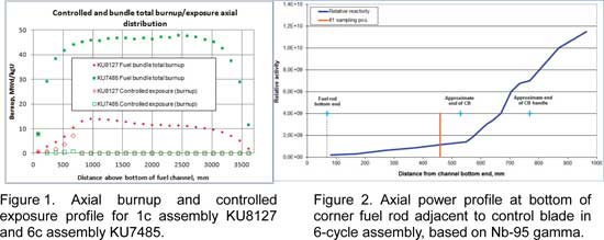
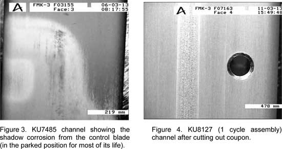
The assembly and channel overall operating history is summarised in Table 1. The node-wise axial burnup distributions of the 1-cycle fuel bundle KU8127 and 6-cycle fuel bundle KU7485 are shown in Figure 1 together with the equivalent controlled exposures for each node. The nodal controlled exposure is the cumulative burnup for the node for that time in which the control blade (or its handle) has been inserted into that node. This metric is equally weighted irrespective of when in life the control blade has been present in the node. As can be seen in Figure 1, for both assemblies/channels there was zero control blade exposure above the lowest 5 nodes at any time in the fuel lifetime. In the lowermost node (node 1) the controlled exposure is equal to the total burnup in that node – this is because with the control blade fully withdrawn (parked position) the control blade handle extends into the first node, so irrespective of the control blade position this node experiences “control”. The shadow corrosion formed from proximity to the control blade handle in the withdrawn position is clearly seen in the lower part of the 6c channel (Figure 3). For the 1c assembly KU8127 the controlled exposure in nodes 2-5 is almost as much as the total burnup, since those nodes only experienced about 70 days of uncontrolled operation prior to the partial blade insertion. For the 6c assembly KU7485 the controlled exposure in nodes 2-5 is much lower than for the 1c assembly since this assembly operated at a much lower power during cycle 24B (it had a higher burnup and was on the core periphery), and represents only a very small fraction of the total burnup for these nodes, see Table 2. It should be noted that the 6c assembly KU7485 was located on the core periphery for its last 3 cycles, so the control blade corner faced inwards. The assembly achieved a burnup of 35.2 MWd/kgU during its first 3 cycles, but only an additional 5.9 MWd/kgU in its last 3 cycles on the periphery. Nonetheless, the fuel rods at both sides of the assembly (adjacent to the channel sampling positions) had similar end of life burnups and so the channel fast neutron fluences were probably relatively similar on both sides during the first 3 cycles and only differed much in the last 3 cycles.
Figure 2 shows the axial power profile in the lower part of the corner fuel rod adjacent to the control blade corner (a1 rod) during the last cycle of operation, based on Nb-95 gamma spectrometry. The effect of the partially inserted control blade, as well as the control blade handle, are clearly seen.

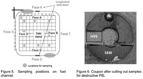
Circular samples (coupons) were cut from the CB (Control Blade) side (Face 4) and the non- CB side (Face 2) beside the longitudinal weld seam, see Figures 4 and 5 below. On each side, coupons were cut at three axial positions: 460 mm, 1930 mm and 3290 mm above the bottom of the channel. A new replacement channel was obtained for the continued operation of the 1-cycle bundle, since its original channel had to be scrapped after the coupons had been cut out.
The coupons were positioned by drilling a pilot hole through the channel wall, marking the upper end with the pilot drill, and then cutting out the coupons with a core drill, see Figure 6 below.
Channel bow measurements were performed on both channels before the sample cutting. The maximum bow was as follows, where a negative value is away from the CB.
KU8127 (1 cycle) x-direction -0.35 mm y-direction -0.46 mm
KU7485 (6 cycle) x-direction +0.98 mm y-direction +2.26 mm
The channel coupons were retrieved from the shipping container, and photographed to rec-ord the inner and outer surface appearance. Hot vacuum extraction (HVE) and scanning electron microscopy (SEM) samples were cut out as shown in Figure 6.
The hydrogen content was measured by HVE using an ELTRA OH-900 Hydrogen Determina-tor as follows: The samples (weighing about 0.1 g) were placed in a graphite crucible and heated up to about 2000 °C with argon as carrier gas. Any CO that might be present was removed by passing the gas mixture through Schütze’s reagent (I2O5) to oxidize the CO to CO2 which was subsequently removed by chemical reaction with NaOH. The gas mixture of argon and hydrogen then passed through a thermal conductivity detector with low drift, high resolution and wide measuring range. The hydrogen concentration was determined by an integrator. Before the measurements, the HVE equipment was calibrated using certified Ti-based standards with 62.5 ± 3.2 ppm hydrogen content. Although the absolute accuracy of the hydrogen determination using HVE is no better than the relative accuracy of the calibra-tion standards (in this case about 5 %), the reproducibility/precision has previously been found to be better than this, except at very low concentrations. The measurements were per-formed on samples which included any attached oxide, so the reported hydrogen concentrations refer to the total evolved hydrogen relative to the total sample weight.
Cross-sectional arcs were cut out for scanning electron microscopy (SEM), where the inner and outer surface could be examined along a plane just above the word “SEM” in Figure 6. The samples were embedded in epoxy resin, ground and polished with 0.04 μm colloidal SiO2 suspension as a final oxide polishing step. The examinations were performed in a JEOL 6300 SEM. Micrographs were taken in BEI-mode (Backscatter Electron Imaging) using dif-ferent instrument settings for optimised imaging of the oxide or the hydrides. The oxide thickness was evaluated from the micrographs acquired in the SEM. The average thickness was determined by measuring the total oxide area in each micrograph using a Leica QWin image analysis software. The oxide area was divided by the width of the measured oxide layer in each micrograph to obtain the average oxide thickness. This method takes into ac-count variations in oxide thickness and delamination or separation of oxide layers.
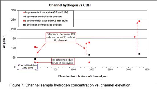
The hydrogen concentrations measured by HVE are shown in Figure 7. The red symbols represent the measurements on the control blade side (face 4 in Figure 5) and the black symbols represent the measurements on the non-control blade side (face 2 in Figure 5). The 1-cycle channel (diamond-shaped symbols in Figure 7) had a low concentration of just over 20 ppm for both the CB side (face 4 in Figure 5) and the non-CB side (face 2 in Figure 5) at the lowest elevation (460 mm above the bottom of the channel). At this elevation the control blade was adjacent to the CB side during cycle 24B. At the mid-height elevation (1930 mm) the hydrogen was only measured on the CB side and was essentially the same as at the lower elevation.
The 6-cycle channel (square symbols in Figure 7) had very much higher hydrogen levels in all the samples measured. On the non-CB side, the hydrogen concentration increased with elevation from just over 40 ppm at the lowest position to just over 70 ppm at the top sample. On the CB side, the hydrogen concentration was very much higher, increasing with elevation from just over 100 ppm at the lowest position to just over 240 ppm at the top sample.
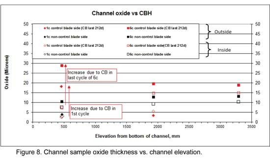
The average oxide thicknesses measured in the SEM are shown in Figure 8. The red sym-bols represent the measurements on the control blade side (face 4 in Figure 5) and the black symbols represent the measurements on the non-control blade side (face 2 in Figure 5). The filled symbols are the oxide thickness on the outside of the channel wall and the open sym-bols are the oxide thickness on the inner surface. The oxide layer appearance (topography) varied between the samples and frequently between the inner and outer surface of the same coupon. The oxide appearance is described qualitatively below.
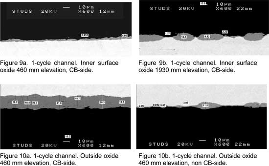
1-cycle channel. The inner oxide layer was rather uniform in both the 1-cycle samples at the lowest elevation but thicker nodules were present at the 1930 mm elevation (Figures 9a and 9b). The outer surface oxide layer was much thicker, and relatively uniform, in the sample that had been adjacent to the control blade (460 mm elevation on CB-side), compared to the other samples (Figures 10a and 10b).
6-cycle channel. The inner oxide layer was rather even in the 6-cycle samples (Figures 11a and 11b). The average thickness was the same on both sides at the 460 mm elevation, and thicker higher up. The outer surface oxide layer was thicker in the sample that had been ad-jacent to the control blade (460 mm elevation on CB-side), compared to the other samples. (Figures 12a and 12b). Both the inner surface and outer surface oxide showed some appar-ent tendency to delamination (cracks) which was not seen in the 1-cycle samples.
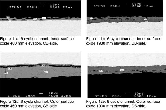
The oxide appearance has been broken down into the following rough categories, and the different sample surfaces are characterized accordingly in Table 3:
“Wavy” where there is a continuous oxide coverage, but the thickness varies signifi-cantly with a wavy appearance, see e.g. Figure 9a.
“Nodular” ” where the individual nodules are about an order of magnitude thicker than the thin oxide separating them, see e.g. Figures 9b and 10b.
“Uniform” where the thickness varies less than about a factor 2, irrespective of the ac-tual thickness or condition of the layer, see e.g. Figures 11b and 12b.
It is considered likely that the wavy or nodular oxide appearance seen in the 1-cycle channel would eventually progress to the continuous oxide film categorised as “uniform”.
Shadow corrosion. The shadow oxide thickness (oxide attributable to the shadow corrosion) can be estimated from the difference in oxide thickness between the CB-side outer surface at the 460 mm elevation, compared to the non-CB side at the same elevation. The shadow cor-rosion can also be estimated from the difference in oxide thickness between the outer surface (facing the control blade) and the inner surface, at the 460 mm elevation. In both cases for the 1-cycle channel, this results in an apparent shadow corrosion during cycle 24B of about 15 µm, as indicated in Figure 8. For the 6-cycle channel, the shadow oxide thick-ness estimated in the same way results in an apparent shadow corrosion during cycle 24B of 18-22 µm, as indicated in Figure 8. It thus seems that the 212 days of exposure to the partial-ly inserted control blade resulted in a somewhat thicker shadow corrosion on the 6-cycle channel than on the 1-cycle channel, despite the fact that the latter had only operated for 70 days prior to the control blade exposure and thus not built up a thick oxide layer prior to the control blade exposure.
This observation is notable when bearing in mind the fact that the 6-cycle channel operated in a far lower radiation field during cycle 24B when the shadow corrosion occurred. Although not a perfect measure of the radiation field, the difference in “controlled exposure” (fuel bun-dle nodal burnup accumulation while adjacent to the control blade) gives some indication of this difference between the two channels. In the controlled node 3 (corresponding to the 460 mm elevation coupons) this parameter was almost an order of magnitude lower for the 6-cycle assembly than for the 1-cycle assembly. Since shadow corrosion is believed to be a form of radiation assisted galvanic corrosion [3], if the radiation field intensity plays a role it might have been expected that the shadow corrosion should have been equal or greater in the 1-cycle channel. However, the exact distance between the control blade surface and the channel might vary slightly from case to case, which could potentially explain the faster shadow corrosion in the 6-cycle channel.
General corrosion. The corrosion on all the sample surfaces from the 1-cycle channel, apart from the surface exposed to the control blade with shadow corrosion, had average oxide thicknesses ranging from just under 3 µm to just over 5 µm at both the 460 mm and the 1930 mm elevation (Figure 8). For the 6-cycle channel, however, there was a more noticea-ble (factor 2) increase in the general oxide thickness from the 460 mm to the 1930 mm elevation (Figure 8). At the 1930 mm elevation both the inner and outer surfaces of the 1-cycle channel had characteristically nodular oxide appearance, see Figure 9b and Table 3. The oxide on the 6-cycle channel at the same elevation had a more uniform appearance, see Figure 11b and 12b. Assuming that the 6-cycle channel had a similar oxide layer at the end of its first cycle to the 1-cycle channel then the subsequent growth of the oxide in the later cycles primarily consisted of “filling in” the oxide layer between the nodules, rather than a further increase in the depth of the nodules.
Hydrogen pickup. The measured hydrogen content in three coupons from the 1-cycle channel all showed low and similar levels of 22-26 ppm, despite the 3-times thicker total ox-ide thickness (inner and outer surface) for the 460 mm sample exposed to the control blade, see Figure 7. There was thus no indication of any additional hydrogen pickup due to shadow corrosion in these channel samples. The 6-cycle channel sample exposed to the control blade, however, had a far higher hydrogen content than the sample from the opposite side at the same elevation, see Figure 7. The difference between the control blade side (face 4) and the opposite side (face 2) was even more striking for the two higher elevations. Since the higher elevations were never exposed to control blade presence, the higher hydrogen level in face 4 cannot be explained by shadow corrosion due to control blade proximity, which has been claimed in other cases [1, 4, 5]. The apparent “hydrogen pickup fraction” for the sample positions where both hydrogen concentration and inner and outer surface average oxide thickness were measured, is shown in Table 3, assuming the oxide has 100% theoretical density.
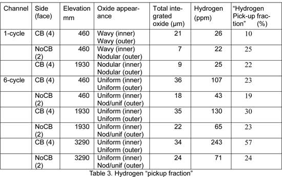
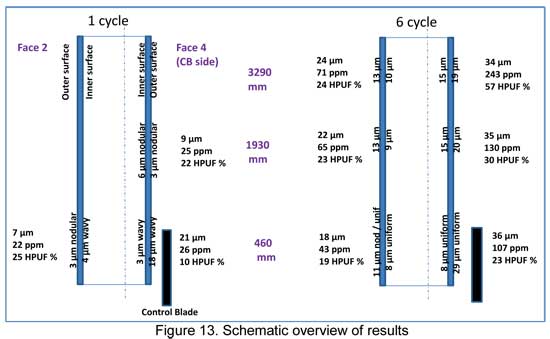
As explained above, it would seem that the shadow corrosion (estimated to be about 15 µm for the 1-cycle channel) did not result in significant hydrogen pickup. Similarly, for the 6-cycle channel, the total hydrogen content in the CB side at 460 mm elevation (which experienced control blade proximity and shadow corrosion) is lower than for the higher elevations on the same side. So what could have caused the higher total hydrogen pickup (and apparent pickup fraction) on the CB side of the 6-cycle assembly compared to the opposite side?
One difference between the two channel sides is that the channel-channel water gap is larg-er on the CB-side (see section 2 above). However, it is not evident that this would affect the hydrogen pickup, since the non-boiling bypass water was about the same temperature on both sides when the assembly operated in more central positions in the core in the first three cycles. Instead, it is more likely that the last 3 cycles when the assembly was in the same core position on the periphery may have had some effect.
The entire assembly had a very low average void in the last three cycles (exit void of about 25 %), with no bulk boiling calculated for the lowest 13 nodes including the 1930 mm eleva-tion, so presumably what void there was occurred mainly on the side facing the core centre (towards the CB sides). The inlet temperature was 275-277 ºC, and since there was no bulk boiling in the bypass the exit temperature on both sides was below 286 ºC. Since the bypass flow area is larger, and the heat flux lower, on the outer facing surface the bypass water tem-perature (and thus channel temperature) was somewhat lower compared to the inboard-facing sides. However, it does not seem likely that the slightly higher bypass water tempera-ture on the CB-side than the opposite side could explain the difference in hydrogen pickup, since the hydrogen content at both the 460 mm and 1930 mm levels on the CB-side were higher than the hydrogen content in the opposite side at higher elevations (where the chan-nel temperature would also have been higher).
The non-CB side had a lower fast neutron fluence than the CB-side during the last three cy-cles, which may provide an explanation for the difference in behaviour. It is possible that although both sides of the channel had experienced substantial irradiation damage during the first three cycles of operation, the outer-facing sides experienced insufficient fast neutron flux in the last three cycles to undergo the rapid increase in hydrogen uptake that is typical for irradiated Zircaloy-2 in in-pile BWR conditions after high exposure.
Neither channel had appreciable bow. The 1 cycle channel had a very small negative bow (i.e. away from the CB corner), remaining from the as-fabricated condition (Forsmark 3 channels are oriented such that any existing bow is away from the control blade). The 6 cycle channel has a small bow towards the CB sides, which is not surprising considering the higher neutron fluence and hydrogen content on those sides.
The results of the post-irradiation examinations showed that:
The shadow corrosion rate was somewhat higher on the 6-cycle channel than on the 1-cycle channel.
For the 1-cycle channel the side adjacent to the control blade and the opposite side at the same elevation had essentially the same low hydrogen concentration, showing that the early-in-life control blade exposure did not cause any significant increase in hydrogen pickup.
For the 6-cycle channel the samples on the side adjacent to the control blade had far higher hydrogen concentrations than the opposite side at the same elevations. This difference was higher at the higher elevation samples than at the elevation directly adjacent to the control blade.
Since the 1-cycle sample from the side adjacent to the control blade had significant shadow corrosion on the outer surface but about the same low hydrogen content as the sample at the same elevation from the opposite side (without any shadow corro-sion), it is concluded that the shadow corrosion from the proximity to the control blade per se does not make any significant contribution to the hydrogen pickup.
For the 6-cycle channel there was a larger increase in the hydrogen concentration be-tween the control blade side and the opposite side at higher elevations, well above the zone in direct proximity to the control blade. Since the difference at the higher el-evations could not be due to shadow corrosion, it is concluded that the higher hydrogen pickup on the control blade side of the 6-cycle channel is probably related to thicker oxide and is due to some other effect of the different conditions on the two sides of the assembly, for instance the local power, fast neutron flux and void distribu-tion.
The authors are grateful to Jesper Kierkegaard for assistance in selecting the candidate channels and insights into relevant aspects of their operation.
“Shadow Corrosion Resulting in Fuel Channel Bowing”. USNRC Information Notice 89-69 Supplement 1, 25 August 2003.
Operating Experience from Swedish Nuclear Power Plants 2008. Kärnkraftsäkerhet och Utbildning AB, 2009.
G Lysell, A-C Nystrand and M Ullberg, “Shadow Corrosion Mechanism of Zircaloy”, ASTM STP 1467, 2005.
S. T. Mahmood et al., “Channel Bow in Boiling Water Reactors – Hot Cell Examination Results and Correlation to Measured Bow”, Proc. Int. LWR Fuel Performance Meeting San Francisco, California, Sept. 30 – Oct. 3, 2007.
http://www.euronuclear.org/e-news/e-news-49/effect-of-stress.htm

Presented during the TopFuel 2015 conference
M.N. CINBIZ
Department of Mechanical and Nuclear Engineering, Pennsylvania State University
University Park, PA 16802, USA
D.A. KOSS
Department of Materials Science and Engineering, Pennsylvania State University
University Park, PA 16802, USA
A.T. MOTTA
Department of Mechanical and Nuclear Engineering, and
Department of Materials Science and Engineering, Pennsylvania State University,
University Park PA, 16802, USA
During vacuum drying operations, spent fuel cladding typically can experience high internal gas pressure loading that can cause the precipitation of dissolved hydrides into a radial configuration which can degrade the mechanical properties of the cladding during dry-cask storage/transportation conditions. Because the stress state experienced by the cladding is multiaxial, this study investigates the role of stress state on hydride reorientation. Zircaloy-4 sheet test specimen configurations were designed to induce a range of multiaxial stress states in material, which was previously charged with hydrogen contents ≈180 wt. ppm. The specimens were subjected to thermo-mechanical treatments designed to form radial hydrides, and the critical stress to reorient hydrides was determined in each case by matching the stress state calculated by finite element analysis at a specific location within the specimen to the hydride microstructures at that location. The results show that the critical value of the major principal stress to initiate radial hydride precipitation decreases from 155MPa to 115MPa as the stress state changes from uniaxial tension to plane-strain tension. Thus, increasing the degree of stress biaxiality enhances radial hydride precipitation, and the effect of stress state should be considered when the assessing the probability of hydride reorientation during drying-operation.
As a result of waterside corrosion reactions hydrogen is picked up by the nuclear fuel cladding during operation in light water reactors. While up to 120 wt. ppm of hydrogen can typically be in solution during operation, when the fuel is removed from the reactor nearly all of the hydrogen precipitates as hydride particles. The precipitated hydride particles can degrade the mechanical properties of the cladding material[1]. In particular, the potential for hydride embrittlement of the cladding tubes increases drastically if the hydride platelets are reoriented from their normal circumferential orientation onto the radial direction of the cladding as “radial” hydrides [2, 3]. Hydride reorientation can occur as a result of heat treatments during the vacuum drying process in which the cladding temperature can reach up to 400°C, causing the hydrides to partially or completely dissolve. During subsequent cool-down, the hydrogen in solid solution can re-precipitate as radial hydride platelets if the hoop stress caused by the internal pressure of the gaseous fission products and fill gases exceeds the threshold stress level for formation of radial hydrides [4]. Hydride reorientation has been studied for either internally pressurized tubes or uniaxial tension testing of flattened tubes with differing thermo-mechanical histories and hydrogen contents [2-8].
The internal pressure within the cladding tube during drying results in a multi-axial stress state within the cladding tube characterized by an axial stress component (minor principal stress) in addition to the tensile hoop stress (major principal stress). There is also the possibility that fuel-cladding interaction may cause an even more complex stress state on a local basis. The influence of a multi-axial stress state on hydride reorientation in cladding material has not been investigated in a systematic manner to date. In this study, the role of stress state on hydride reorientation is assessed over a range of stress states induced by specially designed Zircaloy-4 specimens that are subjected to specially designed thermo-mechanical treatments.
The Zircaloy-4 sheet material in this study was furnished by Teledyne Wah-Chang in the cold-worked stress-relieved condition with a nominal thickness of 0.67 mm, and exhibited a similar crystallographic texture and tensile properties to those of cladding tube material [9]. The experimental procedure for introducing hydrogen was developed by combining the stress-relief anneal with a hydrogen charging treatment. In this procedure, prior to hydrogen charging, the native oxide layer from the surface of the material was first removed using an acid solution, and the specimen was then coated with a 20-nm thick nickel layer to allow hydrogen ingress. A controlled amount of hydrogen-argon gas mixture (12.5% H2 and 87.5% Ar) was subsequently introduced into the chamber (initially at a pressure of less than 13.3x10⁻⁶ Pa) containing the cold-worked specimen at 500ºC. The temperature of the chamber was maintained for 2 hours to simultaneously induce stress relief and to homogenize the absorbed hydrogen through the sample thickness; the specimens were then furnace-cooled. The hydrogen concentration of each sample was determined by hot vacuum extraction. The specimens studied had hydrogen content of approx. 180 wt. ppm.
The as-hydrided microstructure consists of “in-plane” hydride platelets parallel to the sheet surface, analogous to the circumferential hydrides in Zircaloy-4 cladding tube. In order to re-orient the hydride platelets from their normal in-plane orientation into the through-thickness (“radial”) orientation, the specimens were subjected to a thermo-mechanical treatment that consisted of a 2-cycle procedure with an initial cycle consisting of heating at a rate of 5ºC up to 450°C (sufficient to dissolve 180 wt. ppm in Zircaloy-4 [10]), holding at 450ºC for 1hr, and subsequent cooling at a rate of 1˚C/min to 150°C.
Because previous studies have shown that hydride are still in solid solution at 400ºC for hydrogen content of 180wt.ppm[8, 10]), To simulate a possible vacuum drying process[11], when the temperature reached 400ºC during cooling, a constant load was applied to the sample which was maintained until a temperature of 150ºC was reached. This thermo-mechanical cycle ensured that the hydrides were completely dissolved[8, 10] at the maximum temperature for normal operating conditions[11]. The hydride microstructure was examined before and after thermo-mechanical treatments by grinding the samples with successively finer silicon carbide paper followed by etching in an acid solution consisting of 1 part of HF, 10 parts of HNO3, and 10 parts of H2O to reveal the hydrides.
Figure 1 shows the two types of tensile specimens used in this study. Tapered uniaxial tension specimens (Fig. 1 (a)) were machined from Zircaloy-4 sheet with their stress axis oriented in the long-transverse direction of the sheet, which corresponds to the hoop direction of the cladding tube. The taper within the gauge section caused the tensile stress to vary by approximately 45% over the length (13.06 mm) of the gauge section, which had a maximum width of 3.75mm. The length to width ratio of the gauge section exceeded the four-to-one ratio recommended by ASTM for such specimens. [12]
The other type of sample was the double-edge notched “Penn State” flat plane-strain specimen, which imposes a multiaxial stress state on the sample [13]; see Figure 1b. To achieve multiaxial stress state conditions within the tests specimens, Zircaloy-4 sheet with a width of 12.7 mm and length of 40 mm were machined to have a notch opening of 2 mm and a notch radius of 1 mm. This specimen configuration creates a range of multiaxial stress states that can be characterized by the stress biaxiality ratio σ2/σ1, where σ1 is the major principal stress and σ2 is the minor principal stress. The small thickness of the sheet creates a plane-stress condition such that the third principal stress σ3= 0. As shown by finite element analysis a characteristic of the double edge notch specimen is that in the elastic regime, it creates biaxial stress states that vary from σ2/σ1= 0.57 at the center of the gauge section to σ2/σ1= 0 near the notch, as seen in Figure 2. With this knowledge, the effect of stress biaxiality on the radial hydride precipitation can be studied by correlating the hydride microstructure with the local stress state at a given location. In this study, the loads applied to the specimens were in the elastic range for the locations where hydride reorientation was documented.
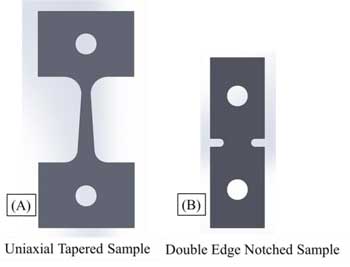
Figure 1. (a) Tapered uniaxial tension specimen and (b) double-edge notched specimen.
The spatial variation of stresses in the double edge notch specimen requires the use of finite element analysis as shown in Figure 2(a) to obtain the local stress values. The threshold stresses for hydride reorientation in double edge notch tension samples were obtained by matching the finite element results and the metallographic images at the same location for the onset of hydride reorientation. The major and minor principal stresses (σ1 and σ2, respectively) were calculated by both two-dimensional and three-dimensional finite element analyses at a known applied load, using the finite element software ANSYS. The Zircaloy-4 sheet material was assumed to have isotropic material properties, and the yield stress at 400ºC of Zircaloy-4 sheet (σy = 300 MPa) was determined by previous studies performed on the same material [8, 9] and confirmed by experiment in the present study. The computed stresses and the stress biaxiality ratio (σ1/σ2) were mapped onto the hydride microstructures in the metallographic images as shown in Figure 2(b). It is important to recognize that both the maximum principal stress σ1 and the stress biaxiality ratio(σ1/σ2)) vary with location within the double edge notch specimen; this feature enables the correlation of a range of stress states with hydride orientations within such a specimen.
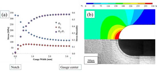
Figure 2. (a) The principal stress and stress biaxiality distribution from notch to center of gauge section; note that σ1/σ2 = 0.57 at the center of the section and σ1/σ2= 0 near the notch. (b) An example of map of the major principal stress with reference to the hydride microstructure.
The threshold stresses were determined to be those stresses calculated at the location where the hydrides are observed to transition from circumferential to radial hydrides. For through-thickness (T-N plane) micrographs, the onset of hydride reorientation was defined as a radial hydride fraction of approximately 0.05 where the radial hydride percentage was estimated by evaluating the orientation of hydrides present in 200x200μm regions using the following relation:

where RHF is the radial hydride fraction, Lri is the length of the ith radial hydride oriented between 45-90° to the transverse direction, and Lci is the length of the ith circumferential/in-plane hydride oriented between 0-45° to the transverse direction.
The “Normal” plane (L-T) micrographs (in which the “face” of the sheet specimen is viewed) identified the locations within the double-edge notched specimen in which the onset of radial hydride formation occurred. The spatial locations of these transition regions were then coupled with the FEA-predicted stress states in these regions; the predicted stress components were based on elements consisting of nine nodes. This procedure enabled the determination of the effect of stress state on hydride reorientation over a range of stress states within each individual specimen.
Both extrinsic and intrinsic parameters affect radial hydride precipitation. Extrinsic parameters include the characteristics of the heating and cooling cycles, the applied stress, and the global stress state of the cladding material. The intrinsic parameters include grain size and orientation, crystallographic texture, degree of cold work, hydrogen content, and initial hydride microstructure[5]. This study focuses on the effect of the global or far-field stress state on hydride reorientation, and more specifically on the threshold stress. In this study, the threshold stress for hydride reorientation in tapered tensile specimens (uniaxial tension) is contrasted to that occurring within double edge notch samples (multi-axial tension).
Figure 3 shows the hydride microstructure in uniaxial tension (σ2/σ1=0) for a tapered tensile specimen containing 180 wt. ppm hydrogen and subjected to the 2-cycle heating-cooling treatment described earlier. The hydrides are observed to transition from in-plane hydrides to radial hydrides at an applied tensile stress of about 155MPa. A high degree of hydride reorientation is achieved above 177MPa, whereas, the radial hydride fraction is equal to zero at stress levels below 147MPa, where only in-plane hydrides are observed in the microstructure. An analysis of this specimen and other similar samples indicates that for the Zircaloy-4 material used in this study the threshold stress to initiate radial hydride precipitation under a uniaxial tension stress state is 155 ± 10MPa.

Figure 3. The hydride microstructure of a tapered uniaxial tension sample after the 2-cycle thermo-mechanical treatment. The threshold stress for hydride reorientation is approximately 155MPa. The image is a through-thickness view of the microstructure.
The hydride reorientation behavior under multiaxial stress states (σ2/σ1>0) was examined by matching the locations of the metallographic images and finite element analysis derived from the double edge notched specimens. Figure 4 depicts both the resulting hydride microstructure after a hydride reorientation test within a double-edge notch tension sample and the stress biaxiality ratio σ2/σ1present during the test at the center plane of the sample and plotted from the center of the specimen to the notch tip. The hydride microstructure in the Figure 4 is that viewed on the “normal” plane which contains both the transverse and rolling directions of the sheet specimen. The “in-plane” hydrides in Figure 4 are oriented parallel to the plane of view, and therefore, they are not observable in the micrograph. However, the “radial” hydrides which are perpendicular to the normal plane of the sample (or parallel to the normal direction) and can be clearly seen.
By examining specimens subjected to a range of applied loads it was possible to assess the locations for the onset of hydride reorientation. As shown in Figure 4, the location within the double-edge notch specimen dictates the local stress state such that the stress biaxiality at the notch is equal to zero (uniaxial tension), but it increases rapidly with distance from the notch such that σ2/σ1=0.57 near the center of the gauge section under the elastic conditions for this analysis. We should note that at other locations near the notch (above or below the minimum width section) the state of stress is also near uniaxial tension, i.e. σ2/σ1≈0. Thus, a range of stress states can be found at various locations within the specimen gauge section. In the present study, the threshold stress for hydride reorientation was determined for a range of stress biaxiality ratios by identifying the location where the onset of radial hydrides occurred and calculating the corresponding stress state at that location for the given load.
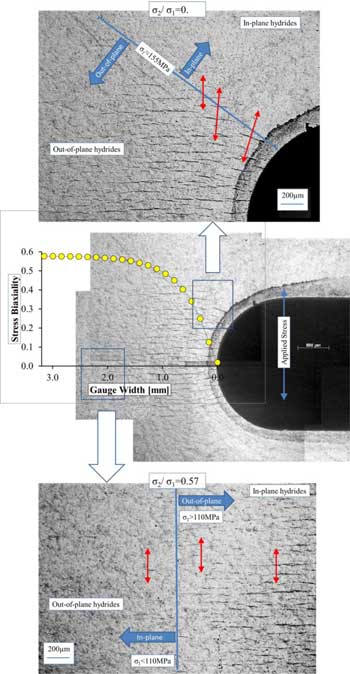
Figure 4. (a)The radial hydride microstructure and stress biaxiality ratio (σ2/σ1) across the gauge section of a double edge notch tensile sample. At the applied stress in this test, radial hydrides are visible in the uniaxial tensile region near notch where the local value of the maximum principal stress exceeds 155MPa (a-1). At stress biaxiality ratio of 0.57, the transition from in-plane to out-of-plane hydrides occurs at maximum principal stress of 110MPa (a-2). The red arrows show the orientation of major principal stress direction at those locations.
Careful analysis of various tests conducted in specimens subjected to a range of applied loads and showing data such as shown in Figure 5 revealed an effect of stress biaxiality on the threshold stress required to initiate radial hydride precipitation. Specifically for a given principal stress, while radial hydrides are observed in regions subject to biaxial tension (σ2/σ1>0), other regions of the specimen experiencing uniaxial tension (σ2/σ1≈0) show no radial hydrides. Consistent with data from uniaxial tension specimens (see Figure 3), an average threshold stress of 155 ± 10MPa is also found at the locations in double-edge notch specimens where there is a uniaxial stress state.
Figure 5 shows the threshold stress variation as a function of stress biaxiality. Three tapered uniaxial tension and five double-edge notched samples, all with approx. 180 wt. ppm. H, were used. For the tapered uniaxial samples, 3-5 measurements from through-thickness micrographs were taken at locations where in-plane to out-of-plane transition occurs. For double edge notched samples, 10 measurements were taken from through-thickness micrographs and 6-10 measurements were taken from “normal” view micrographs.
Figure 5 indicates that the threshold stress to initiate the radial hydride precipitation decreases as the stress biaxiality increases. From the 155MPa-value in uniaxial tension, the threshold stress decreases to 115 ± 7MPa for a stress biaxiality of σ2/σ1 = 0.5, which corresponds to that present in an internally pressurized tube. These results show that radial hydride precipitation is enhanced by multiaxial stress states such that radial hydrides precipitate at lower maximum principal stresses when a minor principal tensile stress is present. Such considerations should be taken into account when evaluating the likelihood of radial hydride re-precipitation during preparation for dry storage as the stress state in that case should be closer to plane-strain biaxial than uniaxial.[14]
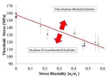
Figure 5. The threshold stress (major principal stress) for the onset of radial hydride formation as a function of stress biaxiality. The specimens contained ≈180 wt. ppm H and were subjected to the described 2-cycle thermo-mechanical treatment described in the text. Each data point is the average of 3 to 5 measurements. Different colors indicate different tests.
Given that this research was conducted on unirradiated hydrided material, it is legitimate to ask whether the results obtained (in particular the sensitivity of the critical stress for hydride reorientation to stress state) are also valid for irradiated material. On the one hand several researchers have demonstrated that hydride reorientation occurs in irradiated material. [15,16] Daum and co-workers have indeed shown that the critical stress for hydride reorientation is the same whether irradiated or unirradiated hydrided material is tested.[17] On the other hand the mechanical properties of irradiated material have been changed because of radiation damage, the presence of irradiation induced defects can provide nucleation sites and the hydride distribution is considerably different because of the temperature gradients present under irradiation. However, because the stress state likely to be prevalent during drying operations of irradiated spent fuel is likely to be between plane strain and equibiaxial tension depending on the degree of bonding between the fuel and the cladding, it would be advisable to investigate the process of hydride reorientation under higher degrees of stress biaxiality.
The effect of the far-field stress state on the threshold stress for hydride reorientation was systematically investigated in Zircaloy-4 containing 180 wt. ppm of hydrogen and subjected to a 2-cycle thermo-mechanical treatment. The analysis of hydride microstructures in both tapered uniaxial and double-edge notch tensile specimens show that the threshold stress to initiate radial hydride precipitation decreases with increasing stress biaxiality ratio. Specifically, the threshold stress decreases from ≈155 to ≈115MPa as stress biaxiality (σ2/σ1) increases from 0 (uniaxial tension) to 0.5 (characteristic of internally pressurized cladding).
This research was funded by the Nuclear Regulatory Commission, under the supervision of Harold Scott. The research for this publication was supported by the Pennsylvania State University Materials Research Institute Nano Fabrication Network and the National Science Foundation Cooperative Agreement No. 0335765, National Nanotechnology Infrastructure Network with Cornell University. Use of the Advanced Photon Source is supported by the U.S. Department of Energy, Office of Basic Energy Sciences under Contract No. DE-AC02-06CH11357. The authors thank Jon Almer and Jun-Sang Park at APS for their help in running the experiments.
R. S. Daum, S. Majumdar, Y. Y. Liu, and M. C. Billone, Radial-hydride embrittlement of high-burnup Zircaloy-4 fuel cladding. Journal of Nuclear Science and Technology, 2006, vol. 43, pp. 1054-1067
Billone, M.C., T.A. Burtseva, and R.E. Einziger, Ductile-to-brittle transition temperature for high-burnup cladding alloys exposed to simulated drying-storage conditions. Journal of Nuclear Materials, 2013. 433(1–3): p. 431-448
Aomi, M., et al., Evaluation of Hydride Reorientation Behavior and Mechanical Properties for High-Burnup Fuel-Cladding Tubes in Interim Dry Storage. Journal of ASTM International, 2008. 5(9): p. Paper ID JAI101262.
Louthan Jr, M.R. and R.P. Marshall, Control of hydride orientation in Zircaloy. Journal of Nuclear Materials, 1963. 9(2): p. 170-184.
Kearns, J.J. and C.R. Woods, Effect of texture, grain size, and cold work on the precipitation of oriented hydrides in Zircaloy tubing and plate. Journal of Nuclear Materials, 1966. 20(3): p. 241-261.
Ells, C.E., The stress orientation of hydride in zirconium alloys. Journal of Nuclear Materials, 1970. 35: p. 306-315.
Chu, H.C., S.K. Wu, and R.C. Kuo, Hydride reorientation in Zircaloy-4 cladding. Journal of Nuclear Materials, 2008. 373(1-3): p. 319-327.
Colas, K.B., A.T. Motta, J.D. Almer, M.R. Daymond, M.Kerr,A.D Banchik, P.Vizcaino, and J.R. Santisteban, In situ study of hydride precipitation kinetics and re-orientation in Zircaloy using synchrotron radiation. Acta Materialia, 2010. 58(20): p. 6575-6583.
Raynaud, P.A., D.A. Koss, and A.T. Motta, Crack growth in the through-thickness direction of hydrided thin-wall Zircaloy sheet. Journal of Nuclear Materials, 2011. 420(1-3): p. 69-82.
McMinn, A., E.C. Darby, J.S. Schofield, Zirc. in the Nuc. Ind.: 12th Int. Symp., ASTM STP 1354, 2000, pp. 173–195
Interim Staff Guidance - 11, Rev. 3, 2003,Cladding considerations for the transportation and storage of spent fuel, U. S. Nuclear Regulatory Commission, Spent Fuel Project Office. 2003.
ASTM, 2001, Standard Methods for Tension Testing of Metallic Materials, ASTM E8-00b, Annual Book of ASTM Standards, vol. 03.01, ASTM, West Conshohocken, PA, 2001, p. 56
Link, T.M., D.A. Koss, and A.T. Motta, Failure of Zircaloy Cladding under transverse plane-strain deformation. Nuclear Engineering and Design, 1998. 186: p. 379-394.
Desquines, J., D. A., Koss, A. T., Motta, B., Cazalis, and M., Petit, The issue of stress state during mechanical tests to assess cladding performance during a reactivity-initiated accident (RIA). Journal of Nuclear Materials, 2011. 412(2): p. 250-267.
Aomi, M., Baba, T., Miyashita, T., Kamimura, K., Yasuda, T., Shinohara, Y., et al., "Evaluation of Hydride Reorientation Behavior and Mechanical Properties for High-Burnup Fuel-Cladding Tubes in Interim Dry Storage," Journal of ASTM International, vol. 5, p. Paper ID JAI101262, 2008.
Chung, H. M., R. S., Daum, J. M., Hiller, and M. C., Billone, "Characteristics of hydride precipitation and reorientation in spent-fuel cladding," Zirconium in the Nuclear Industry: Thirteenth International Symposium, ASTM STP 1423, pp. 561-582, 2002.
Daum, R. S., S., Majumdar, Y. Y., Liu, M. C., Billone, (2006). "Radial-hydride embrittlement of high-burnup Zircaloy-4 fuel cladding." Journal of Nuclear Science and Technology 43(9): 1054-1067.
http://www.euronuclear.org/e-news/e-news-49/PIME2016.htm


Every year, during the PIME (Public Materials Information Exchange) conference, a flagship event organised by the European Nuclear Society (ENS), the PIME Award for Communications Excellence is presented to the creator of what is judged to be the most effective, results-oriented communications campaign launched recently in the nuclear sector.
There is no shortage of awards being presented every day; some might say too many. But there is only one stand-out award that recognises excellence when it comes to communicating on the sensitive and specialised area that is nuclear energy - the PIME Award for Communications Excellence.
So, what is it that makes this award stand out from the crowd? What is its special added value? The answer is peer review. From a professional perspective there is nothing more satisfying than getting the recognition and praise of your fellow communicators, or knowing that your efforts have perhaps inspired them to find solutions to meet their communications challenges. It’s also about sharing with others.
A jury of nuclear communications professionals assesses all the entries and a shortlist of the best ones is drawn up. These shortlisted campaigns are then presented, showcased and “sold” to PIME delegates during the conference. The delegates, your fellow communications professionals, then cast their votes and the winner is determined. The award is presented at the end of the conference.
If you have achieved success with a recent communications campaign don’t keep it to yourself. Share it with others and send it to ENS. If it is shortlisted it will be centre stage during the 2016 PIME Conference, which is taking place in Bucharest, Romania, from 14 – 17 February 2016.
If you know of another communications campaign that is worthy of being entered for the award, but perhaps its creator is too modest, please let us know and it can be assessed too along with all the other camapigns.
You could soon be the proud winner of the 2016 PIME Award for Communications Excellence. It can also provide your organisation with the oxygen of publicity and inspire your fellow communicators around the world to achieve similar success!
Send in your campaign entry NOW and take part in the 2016 PIME Award for Communications Excellence.
MARK YOUR DIARY – Join us in Bucharest from 14 – 17 February 2016
PIME 2016 Conference Secretariat
organised in collaboration with:
http://www.euronuclear.org/e-news/e-news-49/RRFM2016.htm


The RRFM/IGORR 2016 Programme Committee is calling for both oral and poster presentations regarding
Research reactor nuclear fuel cycle - conversion to LEU fuels; fissile material supply; fresh fuel and targets: origin, qualification, fabrication; in-core fuel management and safety; fuel transportation; fuel and reactor licensing; fuel back-end management including reprocessing, spent fuel storage, corrosion and degradation; fuel cycle economics.
Low power research reactors, critical and subcritical assemblies – utilisation, research, education and training programmes, core conversion, licensing, new projects.
Utilisation of research reactors – nuclear science and technology including support for nuclear power programmes; E&T; industrial and medical applications, including radio-isotopes production and irradiation/transmutation technology; research reactor networks and coalitions; strategic and business plans.
Innovative methods in reactor physics and thermo-hydraulics – development and application of advanced computational methods and tools for core load management (operational and safety analysis, and fuel cycle physics); benchmark exercises; nuclear data improvements.
New research reactor projects - national/regional plans or construction updates of new research reactors; lessons learned from new research reactor projects; development of national infrastructures.
Research reactor operation & maintenance and ageing management, – managing reliability issues (commissioning, early operation to end of life related issues); ageing management, modernization, refurbishment, long term operation and life-time extension; maintenance management systems; human resource development and training programmes.
Research reactor safety - implementation of updated international safety standards; review of national regulatory requirements on safety and of licensing activities; design review and upgrades including associated facilities (spent fuel storage facilities); safety analysis methods and approaches; Lessons learned after Fukushima Daiichi and complementary safety assessments.
Research reactor security – implementation of updated international security recommendations; review of national security regulatory requirements; cyber security standards and facility upgrades; security management; review of emergency and contingency plans; interface security; threat assessment and design basis threat in RR security;
Decommissioning and dismantling of research reactors and waste management – strategies and concepts; decommissioning planning; economics; licensing; decontamination and measures to reduce radiation exposure; radiation and environmental protection; treatment, storage and disposal of radioactive waste; logistics and transportation; running projects; D&D lessons learned.
Mark your diaries and be a part of it! Upload your abstracts on www.rrfm2016.org before 6 November 2015.
The abstracts received will be peer reviewed under the auspices of the RRFM/IGORR 2016 Programme Committee. Authors will be notified of paper acceptance by 18 December 2016.
Conference Secretariat
C/o European Nuclear Society
56 avenue des Arts- 1000 Brussels, Belgium
Tel. +32 2 505 30 54 - Fax +32 2 502 39 02
rrfm2016@euronuclear.org
www.rrfm2016.org
http://www.euronuclear.org/e-news/e-news-49/NESTet2016.htm


NESTet is designed to facilitate an exchange of information and the sharing of best practice in nuclear education and training. It is an important networking opportunity for better co-ordination and collaboration between different stakeholders.
The conference targets directors and managers in charge of recruitment and training in companies and research centers, professors, teachers and trainers responsible for devising and delivering education and training as well as coordinators and networkers bringing together stakeholders in nuclear education and training.
Looking to bring together a broad range of experience and best practice, the NESTet Programme Committee is calling for input on the following topics:
Managing the nuclear supply chain: what are employers doing in the workplace to ensure the availability of skills and competences needed? Which methods and processes are applied to manage the internal supply chain? What are critical jobs and competences within the nuclear supply chain and how is this issue managed? What examples exist of effective/successful co-operation between industry, Universities and other stakeholders? What are Universities doing to meet the changing nature of delivery?
How to ensure that enough motivated and competent workforce is available for the nuclear sector? How to encourage skilled professionals with general engineering or project management competence to join the nuclear sector? How to retain skilled workforce? How to ensure skilled workforce in a context of a long-term-exit strategy?
A focus on excellence in project management: we are different! Are we different? What methods and processes are applied to manage key processes and/or complex projects? What are best practice examples? How do organisations build the leadership team´s capacity to successfully lead the organization and to improve performance? How to they organise leadership training? How do they enable leaders to take the right decisions? How do they bridge cultural gaps in an increasingly international industry?
Combining theoretical and practical courses for the comprehensive competence building: what is the contribution of practical courses like laboratory works, experiments carried out on nuclear facilities and exercises carried out on simulators in competence building?
What are the tools recently developed for nuclear education and training? At different levels and with different pedagogical objectives, a broad range of new techniques and tools have been developed for nuclear education and training. These techniques and tools include Massive Open Online Courses (MOOCs), distant learning courses, reactor experiments broadcasted through internet, new software applications and simulators. NESTet 2016 is looking for examples of these new techniques and tools, their application and their feedback.
Generation Y meets Generation III: How to adapt communication, teaching and coaching to the needs and mind-sets of the next generation? How to encourage the choice of STEM subjects in secondary schools and Universities? How to attract young professionals to the sector? How to manage the pedagogical challenges of clashing ages in the nuclear workforce?
Discover the ‘maze’ of networks: What are existing initiatives? Are they beneficial for partners, Universities and/or industry? How can we optimise networking? How can we effectively network with Eastern Partnership Countries to make these networks beneficial for all? How can networks collaborate?
The NESTet Programme Committee welcomes both oral and poster submissions and encourages particularly the presentation of best practice examples.
If you wish to share knowledge and best practice in nuclear education and training in science, engineering and technology, please submit your abstract by 27 November 2015 through the NESTet Abstract Submission System.
Important dates:
Deadline for abstract submission: 27 November 2015
Notification of authors: 30 January 2016
Deadline for full paper submission: 22 April 2016
Deadline for submission of PowerPoint presentations: 6 May 2016
Conference: 22 – 26 May 2016
NESTet 2016 Conference Secretariat:
Tel: + 32 2 505 30 54
Fax: +32 2 502 3902
e-mail: nestet2016@euronuclear.org
www.nestet2016.org
http://www.euronuclear.org/e-news/e-news-49/ENC2016.htm


ENC 2016 provides a platform for the nuclear science community to share their experience and to learn about the latest developments going on in nuclear research and their practical applications. It will furthermore exploit synergy among scientists, industry representatives, policy-makers and citizens on wider societal issues that impact upon how the nuclear science community carries out its work.
ENS and the ENC 2016 Programme Committee are now calling for abstracts in the following areas:
Nuclear science applications for industry and society
Silicon doping; neutron activation analysis including PGAA and delayed neutron detection; isotopes production and supply; water desalination; heat cogeneration; sterilisation; hydrogen generation; non-destructive testing including neutron radiography and tomography; nuclear in space; instrumentation; geochronology, gem stone coloration;...
Life science applications
Radiation protection; low-dose research; environmental studies; diagnostics and therapeutic applications; development of new radiopharmaceuticals; instrumentation; ...
Advanced reactor technologies
Innovative technologies for Generation III+ reactors; Generation IV reactors; small and modular reactors; innovative reactor concepts, including the Thorium cycle; research reactor and testing facilities; fusion reactors; nuclear data; space propulsion reactors; naval civil reactors; floating nuclear plants; …
Current reactor technologies and new build
Creating the framework for newcomers; localisation; stakeholder involvement; socio-economic impact; development of competences, development of a safety culture; licencing; regulation and supervision; regulator recruitment in an expanding industry; innovative construction and engineering; innovations in the supply chain or construction engineering; training methods and experiments for new coming countries; funding issues; managing budgets and planning; strategic export control;…
Plant operations
Operation and maintenance; operation support systems; control room design review; human and organisational factors; instrumentation and control; plant life management; equipment and component obsolescence; material technology and testing; fuel surveillance; meeting grid requirements; lessons learned; plant software simulators; reactor physics software simulators; long term operation; …
Nuclear Fuel
Front end; fuel materials; in core management and fuel behaviour; management of fuel leaking; improved fuel performance; used fuel management; used fuel inspection; long term resource management; uranium and plutonium recycling; partitioning and transmutation; transport of fuel; thorium fuel;…
Waste management, dismantling and decommissioning
Waste management; interim storage; waste segregation, exemptions and recycling; surface and geological disposal facilities; material – host rock interactions; decommissioning; decontamination; dismantling; rehabilitation; regulations; socio-economic impact;...
Safety and Security
Safety management; continuous improvement of safety culture; cyber security; implementation of updated international safety standards; review of national regulatory requirements on safety and of licensing activities; design review and upgrades including associated facilities (spent fuel storage facilities); safety analysis methods and approaches; implementation of updated international security recommendations; review of national security regulatory requirements; security management; review of emergency and contingency plans; interface security; threat assessment and design basis threat; instrumentation; managing severe accidents beyond design conditions; impact of European stress tests; ...
Education, training and knowledge management
Initiatives in education, training and knowledge management; education & training facilities; knowledge transfer; new skills requirements; human capital development; human performance and safety culture; non-destructive testing: personnel qualification and certification; training results: evaluation methodologies; international collaboration; recruitment and labour market issues, e-learning; training simulators; ...
Public engagement for nuclear
Public information; including communicating on nuclear events, nuclear and the societal debates, including and at international fora, nuclear and social media, public perception, stakeholder involvement, economical aspects of nuclear, including CO2; nuclear liability and insurance; countries’ perspectives on nuclear energy policy; international initiatives and projects,...
Upload your abstracts before 1 March 2016
on www.enc2016.org
or contact enc2016@euronuclear.org for further information
Important dates:
Deadline for abstract submission: 1 March 2016
Notification of authors: 30. April 2016
Deadline for submission of Full Papers requesting a peer review: 30 June 2016
Peer review of Full Papers concluded and author notification: 31 August 2016
Deadline for submission of Full Papers and Extended Abstracts: 15 September 2016
Deadline for submission of PowerPoint presentations: 1 October 2016
ENC 2016: 9 – 13 October 2016
ENC 2016 Conference Secretariat:
Tel: + 32 2 505 30 54
Fax: +32 2 502 3902
e-mail: enc2016@euronuclear.org
www.enc2016.org
http://www.euronuclear.org/e-news/e-news-49/sne-news.htm


A one-day technical session of the Spanish Nuclear Society (SNE) was held on 15 April 2015 with a significant participation from the sector and was attended by approximately 100 people. As in recent years, it was organized by the Technical Commission of the SNE. The Session was held at the “Centre Tarraconense El Seminari” in Tarragona. The title of the Technical Session was: Parts Supply in nuclear power stations.
As seen by the numbers of participants and their great interest despite the obvious overload of information in such a tight schedule, the session was a big success which shows the relevance of the chosen topics.
Young Nuclear Generation is actively engaged in boosting interest in education and training of students and young professionals with its Annual Seminar on Safety of Advanced Reactors at the Faculty of Industrial Engineering at the Polytechnic University of Madrid and two Basic Nuclear Science and Technology Courses which took place in the University of Zaragoza and at the School of Engineering at the University of Oviedo. Furthermore, the Young Generation supported the Nuclear4Climate initiative at the ENYGF-Paris-2015.
Nuclear España, the monthly magazine of the SNE, distributed since 1984, has published issues 357 and 361 about the “40th Annual Meeting” and the winter session "Spanish Nuclear Power Plants in 2014: Experiences and Perspectives", in both English and Spanish.
SNE has released the candidates for its annual scholarship grants for Masters programmes related to nuclear technology. To be used exclusively to cover their academic registration cost, up to a limit of €3.000, a total of €22.500 € were assigned.
SNE announced the 2015 edition of the Projects and Master’s Award with content related to science and / or nuclear technology. The three finalist projects were publicly announced on 6 May 2015 and these projects were presented at the 41st Annual Meeting in A Coruña. The winner will be awarded €1,500 plus a commemorative plaque.
SNE signed the international agreement "Nuclear for Climate” declaration in Nice with 40 other nuclear associations from around the world.
Jose Ramon Torralbo, SNE President, signed the "Nuclear for climate” declaration to achieve international recognition of nuclear power as part of the solution to fight change climate.
The ratification of the agreement occurred during the ICAPP conference (International Conference on Advanced Reactors), held in Nice, where the main international experts participated in technology and nuclear energy.
The 41th Annual Meeting of the Spanish Nuclear Society was held on 23-25 September 2015 in A Coruña, Spain. All the relevant information about the meeting is available at: www.reunionanualsne.es. This year over 600 professionals took part; 39 technical sessions conveyed the industry’s projects and advances through 345 papers dealing with areas such as nuclear safety, radiological protection, nuclear fuel, plant operation and maintenance, engineering, R&D, communications, etc. 32 stands representing companies in the industry were at the exhibition.
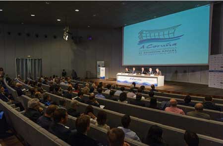
The technical programme included Three Plenary Sessions and a Colloquium Session dedicated to the relevant current issues related to energy subjects and associated issues. The participants in these sessions included high-ranking prestigious national and international experts in the topics covered by the sessions.
The Plenary Sessions focused on currently important issues in the energy and nuclear
sectors such as:
The needs of research, development and innovation to meet the challenges of the nuclear sector: long-term operation, fuel management and new projects;
Intelligent management of cities: a new model of energy supply;
IAEA report on the Fukushima Daiichi accident;
The colloquium Session for experts was on entitled: “How to define the Spanish energy strategy?”
The key part of the technical programme was the Technical Sessions and Worshops, in which national and international professionals and experts presented their work on relevant projects and scientific studies and on the progress made in the past year in different fields. The technical papers were presented in oral and poster sessions. The subjects of the papers covered a wide range of fields such as fusion, O&M, engineering, safety, waste, R&D, communication, medical applications, etc.

The meeting also included activities aimed at informing and educating the general public; e.g. the Basic Course on Nuclear Science and Technology, which was organized by the SNE’s Nuclear Youth Committee and was open to students from the city and region and to anyone else who wished to learn more about nuclear energy and technology.

WiN Spain
Among the activities planned to celebrate its 20th Anniversary, Women in Nuclear Spain attended the Joint Meeting of the Spanish Radiological Protection Society (SEPR) and the Spanish Medical Physics Society (SEFM), held in Valencia on 23-26 June.
A specific WiN session on "Radiation, Health and Nutrition” was organized on 26 June, at Torrent, near Valencia, which was attended by a large representation of the consumer association Tyrius and the Association Against Cancer, as well as professionals of the University and Polytechnic Hospital “La Fe” and the Health Research Institute “La Fe”.
WiN Spain also organized the Conference Session "Industry and Nuclear Medicine in Cantabria", hosted by the University of Cantabria, on 8 July.
http://www.euronuclear.org/e-news/e-news-49/nuclear-institute.htm


On 10 September 2015, the Nuclear Institute (NI) and the Atomic Energy Society of Japan signed a memorandum of understanding at a ceremony held at the Embassy of Japan in London.
The focus of the MOU is on improving international ties and promoting nuclear professionalism by raising awareness of the importance of the individual in safety and security culture.
The new agreement sets out a programme for increased collaboration between the two organisations with workshops taking place in both the UK and Japan to be supported by both organisations across the coming years beginning in 2016.
This is the second such agreement to be signed by the two organisations and provides the basis for a reinvigoration of the close working ties created under the first memorandum.
John Warden, CEO of the Nuclear Institute, said: “The Nuclear Institute values global partnerships with fellow professional bodies and we look forward to building on our ongoing relationship with AESJ.”
The Memorandum was signed on behalf of the Nuclear Institute by past-President of the Institute Norman Harrison: “I am delighted to sign this updated MOU on behalf of the Nuclear Institute. This partnership strengthens the nuclear industry’s ethos of international collaboration which is vital to ensuring efficiency and innovation, and most importantly safety and security for the nuclear sector and the public. I look forward to seeing the broad range of initiatives and events which will arise from this in the future.”
The signing took place during a full day of joint Japan-UK discussions comprised of the ‘Japan-UK Decommissioning Roundtable: A Strategic Vision for Fukushima Daiichi NPP’ and the ‘Japan-UK Nuclear Research Collaboration Symposium 2015’. The events of the day were aimed at increasing international cooperation and collaboration in the nuclear sector and were attended by important members of industry, research and academia from both nations.
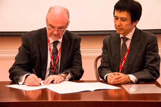
http://www.euronuclear.org/e-news/e-news-49/SNUS.htm


The first three days of October 2015 were devoted to technical visits organized by the Slovak Nuclear Society (SNUS) for its active and deserving members. The aim of the excursion was to visit the maintenance training center at Paks nuclear power plant and the subsurface storage of low- and intermediate-level radioactive waste in Bátaapáti, Hungary.
Shortly after midnight on the first day, the group from Slovakia set out to visit Paks nuclear power plant. The visit began at 9:30 am on that day. The Paks Maintenance Training Centre is one of the top facilities of its kind. Its uniqueness lies in the fact that the practical training of plant personnel and suppliers of major components have the opportunity to perform exercises on real devices. These components include reactor pressure vessel and its internals, steam generators, main circulating pumps, the main shutoff valves and fuel assemblies obtained from Poland and the former GDR from plants that were never built or brought into service (e.g. Zarnoviec and Greifswald).
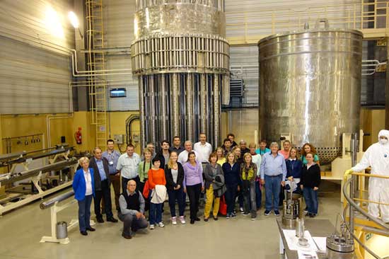
Participants saw reactor internals in the Paks Training center…
It was interesting to see the internal parts of the reactor, but also to have the opportunity to climb to the primary collector of the steam generator. The maintenance staff uses these facilities to train for all activities that are carried out at the time of maintenance outages. In three-year cycles, about 1,500 nuclear power plant employees and about 5,000 employees of contractor organizations pass the training. The training center includes workshops for work on rotating machinery, electrical equipment (including operating voltage), pressure equipment and various valves. A special workshop is established for training, defectoscopy and diagnostics.
Further, we moved to the village of Bátaapáti, where we spent two hours at the national sub-surface repository for low- and intermediate-level radioactive waste. A visit to the facility started at the modern information center of the repository, which opened in August this year. We were confronted with interactive displays using modern teaching techniques to portray information about the creation and storage of radioactive waste, as well as matters relating to security and cooperation in the region. After the visitor’s center, we moved to the technological premises where the radioactive waste (imported from Paks NPP) is encapsulated into drums and fixed into fiber-concrete containers. We then travelled by bus to the storage chambers, which are located at a depth of about 200 m below the surface, where are the fiber-concrete containers are stored.
workshop of rotating machines
We send out a special thanks to SNUS, which supported the excursion; Mr Josef Markus, who organized the expedition; and Mr Betka Füri who helped us in communicating with our Hungarian colleagues.
In front of Siklós Castle
http://www.euronuclear.org/e-news/e-news-49/romania.htm

The Romanian Nuclear Energy Association (AREN) and the Romanian Atomic Forum (ROMATOM) organized in 2015 a children drawing competition entitled “Alexandru Ene”, and an essay contest “The Atom – Our Friend”. Already a tradition, the drawing and essay contests saw a considerable number of participants, eager to enter the battle of creativity.
The success of this competition was also confirmed by hundreds of participants from all over the country. All participating children with a talent for writing or drawing illustrated their knowledge, perception and views on the “omnipresent atom”.
“We wanted to grant equal opportunities for those students with outstanding talents for drawing as well as for those guided only by inspiration and creativity in handling the brush. For more objectivity and transparency in judgment, the contestants were divided into three age categories: 7 – 10, 11 – 14, and 15 – 19 years old. They competed according to their specific educational unit”, stated Mrs. Mihaela Stiopol, President of AREN.
Almost 200 illustrations entered the drawing competition, out of which more than one quarter originating from schools specializing in fine arts. Although the essay section received fewer papers (only 36 essays), this section showed the most inspired literary creations. The submissions for both categories met the assigned theme and tried to convey, as close as they could, the importance of the atom related to all discoveries which have impacted our lives today.
This year’s jury consisted of five members with experience in nuclear engineering, architecture, communication and advertising. The quality, originality and creativeness of the works turned the judgment process into a disputed one. At the end of the evaluation and adjudication process, there were 24 prizes awarded.
The competition ended on 5 June 2015, with a piano concert and an exhibition hosted by the George Enescu Museum (Cantacuzino Palais), where all participants received an award, not only the winners of the competitions. Moreover, all the entries in the competition were exhibited. Thus, for two days, everyone present (including tourists, children and parents) could admire the drawings.
“We thank all the children, from all over the country, who participated in this year “Alexandru Ene” drawings and essays contest. We also appreciate the interest, desire and creativity they showed in presenting and converting the atom into the nucleus of their artistic works’ universe”, stated Livia Chitu, RYG Vice Chair.
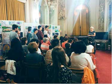
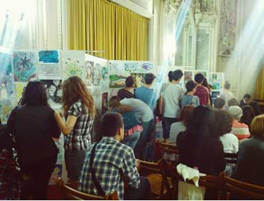
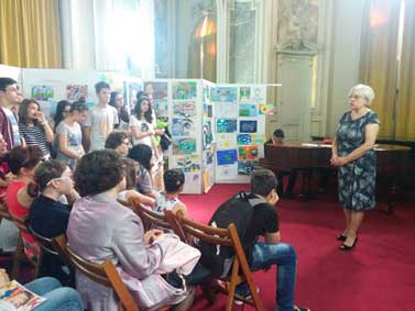
http://www.euronuclear.org/e-news/e-news-49/Nuclear-2015.htm


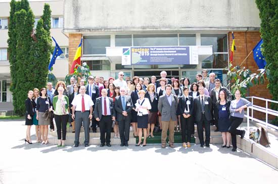
The annual international conference NUCLEAR 2015, held in May in Pitesti, Romania, aimed to:
promote nuclear energy as part of the energy mix, contributing to a secure energy supply and reducing greenhouse gas emissions;
bridge research and academia in this field;
acquire the political support for priority nuclear projects;
increase the visibility of nuclear research developed in this region and enhance collaboration.
The conference organized and hosted by the Institute for Nuclear Research (INR) Pitesti gathered more than 200 participants representing the entire spectrum of actors involved in nuclear energy in Romania, the EU and abroad. Each year, at the end of May, INR becomes the meeting point for international scientists and specialists from top organizations in the nuclear field, representatives of the IAEA, European Commission and Technological Platforms, important actors of European nuclear industry and academia, as well as local and national politicians.
Through the last seven meetings, the conference closely followed the top priorities and challenges of nuclear energy, contributing to constructive dialogue and information exchange between key actors in the decision making process, research, industry and academic communities.
The 8th edition of the conference contributed to a better knowledge and understanding of the European Commission policies in research, and to a wider dissemination of the visions and research agendas shaped by the Technological Platforms, playing a role in the constant increase of cooperation among the research centers in the Central and Eastern region and their participation in Euratom Framework Programmes.
The Conference contributed to building relationships between the nuclear research community and academia, opening up dialogue on the research challenges and on the special job requirements for the field of nuclear energy. The 2015 conference gathered over 100 contributions, including lectures provided by key speakers on the most important topics of nuclear energy.
NUCLEAR 2015 gave particular importance to the European efforts dedicated to the new generation of nuclear reactors, with a particular focus on lead-cooled fast reactor (LFR) technology, the preparation of the national R&D programmes for Horizon 2020 research in nuclear energy, and participation in European Joint Programming.
http://www.euronuclear.org/e-news/e-news-49/energy-for-humanity.htm


Kirsty Gogan, Director & co-founder of Energy for Humanity
In 2013, the documentary film Pandora’s Promise shattered the long-standing taboo against discussing nuclear energy as an environmental positive. The film created a safe space for nuclear supporters to speak out, and shifted the discourse on nuclear energy. The success of Pandora’s Promise illustrates a tremendous gap in the nuclear education & advocacy space – the need for a strong, independent voice articulating the need for nuclear.
With enthusiasm from Pandora’s Promise still high, but the film’s campaign coming to a close, Film Director Robert Stone, Daniel Aegerter and I co-founded Energy for Humanity (launched in October 2014), to fill that gap.
Our values are that we are global in scope, optimistic, independent and profoundly committed to improving quality of life for all people.
A key target on our path to limit the world’s temperature increase below 2°C in 2050 is that at least 80% of the world’s electricity must be low-carbon by 2050.
Our main goal in the 21st century should be to replace coal. And yet, here we are: 25 years after the world was first alerted to the need to dramatically reduce carbon emissions or irreversibly alter the Earth’s climate system, and coal remains not only the world’s no.1 source of electrical energy but the fastest growing.
Why is this? The problem is that compared to nuclear plants, which are capital intensive and politically extremely complicated, coal is abundant, quick and easy to build, with little risk for the developer or operator.
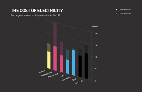
Nevertheless, while it’s very difficult to make future cost estimates, many studies show nuclear is the most cost-effective way to cut carbon from large scale electricity generation, as you can see from the graphic above using data from a UK Energy Research Council report. This is also consistent with the recent IEA/OECD NEA report on electricity costs. And this does not include system costs, which means the costs associated with additional grid connection for low-density renewables, or back up capacity for variable renewables. There is considerable research now showing that these system costs become very significant above 30% penetration.
You can see nuclear is the yellow bar on the left, even comparing with coal, nuclear proves to be extremely good value. The difference is the very high up front capital costs, as well as other political risks, whether regulatory, or in terms of public perception, that make financing nuclear plants very challenging.
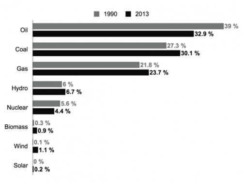
Sources of world’s energy in 1990 and 2013 - Source BP World Energy Outlook
The result is that, as this graph by Climate Gamble shows, while oil use has (relatively speaking) fallen somewhat, coal use has increased compared to 1990. This despite all the promises and negotiations that have aimed at reducing CO2 emissions, of which coal burning is the largest single culprit. We can also see that while renewables have shown commendable progress, their shares are still very small of the total.
It’s tempting to think that we could reduce our carbon emissions simply by saving energy. But it would be a mistake to over-estimate the role that energy efficiency can play in meeting our carbon reduction targets. Electricity consumption is forecast to grow, and we hope that it will.
At present, the majority of environmentalists insist that decarbonisation can be achieved entirely by accelerating the deployment of renewable energy (particularly wind and solar) coupled with dramatic improvements in energy efficiency. Nuclear energy, they say, is simply not necessary to effectively tackle climate change. But just consider the mountain we have to climb when right now wind power provides just 2 per cent of global electricity, and solar just half a per cent! Solar may be the fastest growing source of renewable energy, but coal is the fastest growing source overall, full stop.
If we are serious about tackling climate change, no climate-neutral source should be ignored. That means all the tools in the box: renewables, including hydro and variable sources of power like wind and solar, as well as nuclear and carbon capture and storage. We are especially interested in nuclear since it’s one of the few options available at scale to reduce CO2 whilst providing “baseload” power. “Baseload” means always on, around the clock, whatever the weather.
The Economist newspaper recently asked the question: Which policy actions so far have made a quantifiable difference to cutting carbon emissions? The answer is surprising: Montreal protocol is number one, cutting equivalent emissions by more than 5 billion tons. Hydro power and nuclear energy are numbers two and three. Head and shoulders above anything else. Interestingly, the Chinese one child policy is number 4 on the list, cutting emissions by more than a billion tons.
So nuclear is already making a huge contribution. Nuclear is already a significant source of low carbon power – avoiding the release of 56Gt of CO2 equal to almost two years of total global emissions since 1971.
So while we may think it’s stating the obvious to say that nuclear power is extremely low carbon, with no emissions in operation. Many members of the public do not know that nuclear energy is similar in its emissions to wind and solar.
Nuclear is also an extremely dense source of power, which means a tiny footprint of land for an extremely large output: comparing the land take required to deliver 26TWh per year from nuclear, wind farms or solar farms would amount to 10’s of thousands of acres.
Because the UK has legally binding climate change targets to reduce overall emissions by 80% by 2050, cross party consensus has been achieved that all available technologies should be included. Nuclear is a key plank in the UK low carbon energy strategy, with a 16GW programme of new build planned. Nuclear is seen as not only low carbon, but also reliable and cost effective.
The electricity market has been reformed to create incentives for capital intensive low carbon infrastructure. Today our Chancellor is in Beijing announcing new collaborations between the UK and China to expand clean nuclear energy production.
However, the mantra 'nuclear can't be done quickly enough to tackle climate change' is one of the most pervasive in the debate today and mostly just taken as true, while the data prove the exact opposite.
Just 6 countries in the world have achieved the goal of taking carbon out of their electricity generation. Iceland has geothermal, Norway has hydro, and four countries have achieved the target through a combination of renewables and nuclear: France, Brazil, Switzerland and Sweden.
Let’s look at Sweden. In just two decades Sweden went from burning oil for generating electricity to fissioning uranium.
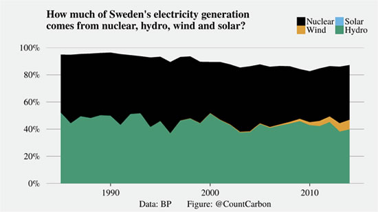
Research by Dr Barry Brook and Dr Staffan Qvist, published in May this year and based on World Bank data, shows that this appears to be the most rapid installation of low-CO2 electricity capacity on a per capita basis of any nation in history (France and the U.S. installed more total nuclear capacity in the 1960 to 1980s, but less than Sweden on a per capita basis).
“No other carbon-neutral electricity source has been expanded anywhere near as fast as nuclear.” Barry Brook and Staffan Qvist
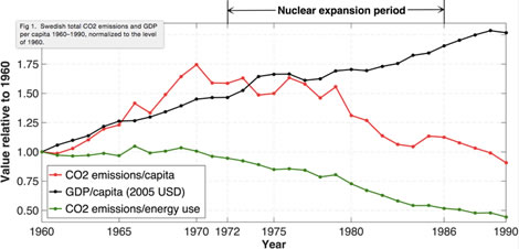
So these researchers argue that Sweden provides a historical benchmark ‘best-case scenario’ on which to judge the potential for future nuclear expansion.
If the world as a whole were to follow that example, all fossil fuel–fired power plants could be replaced with nuclear facilities in a little over 30 years.
And in terms of costs: Nuclear electricity costs in Sweden have always included a surcharge corresponding to the full estimated costs of researching, building and operating a final repository for all nuclear waste. At the end of the nuclear expansion period, Swedish electricity prices (including taxes and surcharges) were among the lowest in the world, and the running cost of the nuclear plants (per kilowatt hour [kWh] produced) were lower than all other sources except for existing hydropower installations.
No renewable energy technology or energy efficiency approach has ever been implemented on a scale or pace which has resulted in the magnitude of reductions in CO2 emissions that is needed to avert catastrophic climate change.
Real world data shows that a replacement of current fossil fuel electricity by nuclear at a pace which might limit the more severe effects of climate change is technologically and industrially possible.
The projection that fossil fuel electricity generation could be replaced by nuclear globally within 30 years is grounded in reality, being based on actual historical experience rather than speculation on future technological and cost developments.
Whether this will happen depends primarily on political will, strategic economic planning and public acceptance.
It is for these reasons that nuclear must be acknowledged as a proven, scalable strategy for carbon reduction, and included in the climate negotiations at COP21 in Paris this year.
http://www.euronuclear.org/e-news/e-news-49/hungary.htm

The members of society participated in several summer festivals (including the famous “Sziget” festival) with the „nuclear tent”. The visitors – mainly young people – could get detailed information on nuclear topics, e.g. basic physical phenomena, radiation, the status of building new nuclear power plants in Hungary and the perspectives of nuclear fusion for electricity production.
Considering the construction of two VVER-1200 units at the Paks NPP, the Society invited two Russian experts to discuss the technical aspects of reactor building. The experts informed the Hungarian audience on the basic characteristics and safety features of new units and on the modern computer based methods that will be used during design and construction. The speakers said that the first steps of design for the Paks site have already been completed by the Russian institutes.
 |
 |
 |
The environmental group of the society organized seminars on the “Evaluation of risk in energetics” and on the “Evaluation of environmental consequences of energy-mix” with the participation of domestic experts.
The representatives of the Society signed the Nuclear for Climate Declaration, the Position Paper on Nuclear Energy and the Environment of the European Nuclear Young Generation Network and the Women in Nuclear Declaration for the Earth’s Climate at different international forums.

http://www.euronuclear.org/e-news/e-news-49/iync2016.htm

The call for summary submissions for the IYNC2016 conference to be held in Huangzhou, China, is now open.
Authors are asked to submit directly a minimum two-page (max four pages) summary, which will be reviewed for relevance and quality. See instructions in the following template.
Summaries may be submitted for the following sessions:
NPP Operation and Maintenance, Design Modification
Advanced Reactors Design (including Gen IV)
Reactor Physics and Neutronics
Thermal Hydraulics
Nuclear Fuel and Materials
Nuclear Safety, Security, Safeguards (including non-proliferation) and Radiation Protection
Nuclear Fuel Cycle, Waste Management and Decommissioning
Fusion
Education, Human Resources Development and Knowledge Management
Politics, Economics, and Societal issues
Applications of Nuclear Technology in Non-power Sectors
YGN best practices

When submitting the summary, authors can express their preference for oral presentation or poster session. The organization will ultimately decide on the way it is presented.
Over 100 high quality full papers will be selected and published in a special issue of Energy Procedia (A peer-review Journal indexed by Scopus, Thomson CPCI and Ei). There will also be awards for the best presentations and posters.
November 15th 2015:
Summary (2-4 pages) submission deadline
December 15th 2015:
Summary acceptance
March 15th 2016:
Full paper (5-8 pages) submission deadline
April 15th 2016:
Full Paper review notification
May 15th 2016:
Revised full paper deadline
For any further information please visit our webpage:
www.iync.org/call-for-summary/
IYNC2016 will be held in Hangzhou, China and will bring together more than 700 young and senior professionals, students and academia. IYNC2016 will feature plenary sessions, interactive workshops, technical tracks, a large variety of technical tours and networking activities. In the spirit of a volunteer organization, we are seeking corporate and organizational sponsors and exhibitors who believe in the future of the nuclear industry and in the potential of the next generation. There are six levels of sponsorship: contributor, bronze, silver, gold, platinum and diamond, with an increasing level of benefits to the sponsor. We will give your organization the recognition you deserve!
More sponsorship information:
Nicolas ANCIAUX
Corporate Sponsorship Chair
E-mail: nanciaux@iync.org
TAN Ke
Local Sponsorship Chair
E-mail: tanke@cgnpc.com.cn
![]() IYNC 2016 Sponsorship information
IYNC 2016 Sponsorship information
http://www.euronuclear.org/e-news/e-news-49/l-3.htm

L-3 MAPPS announced that it has won an order from Westinghouse Electric Company to deliver a full-scale 1,000 MWe class pressurized water reactor (PWR) simulator equipped with severe accident simulation capability as part of a larger project that Westinghouse is fulfilling for a customer in Tokyo, Japan. The simulator will be used to teach operators plant responses ranging from normal operations to severe accidents. It will be in service in the first quarter of 2016.
“Westinghouse and L-3 MAPPS have a rich and long history of working together to enable Westinghouse control systems with L-3 MAPPS-developed plant simulators in the U.S. and in Europe,” said Scott Roberts, Director of operator interface for Westinghouse.
“L-3 MAPPS is committed to making a contribution to nuclear safety with this new project,” said Michael Chatlani, Vice President of marketing & sales for L-3 MAPPS Power Systems and Simulation. “The project is L-3 MAPPS’ first sale into the Japanese market and we look forward to further developing our relationships in this region.”
The simulator will be based on L-3’s latest fully integrated Orchid® simulation environment and will operate within a virtual control room implemented using the Orchid Touch Interface and Orchid Sound System solutions, providing a full-scale training environment. The virtual panels and Orchid Instructor Station will be made available in Japanese to facilitate operation of the PWR simulator.
L-3 MAPPS will also connect the Electric Power Research Institute’s (EPRI) Modular Accident Analysis Program (MAAP5) to the simulator. The simulator models will include support for the connection of external power and water sources, part of the diverse and flexible (FLEX) response strategy developed by industry to address challenges experienced at the Fukushima Daiichi power station following the earthquake and tsunami on March 11, 2011. MAAP5 is a software program that performs severe accident analysis for nuclear power plants, including assessments of core damage and radiological transport.* The simulator will also be equipped with new two-dimensional and three-dimensional animated, interactive visualizations of the reactor vessel, containment building and spent fuel pool to provide trainees with additional insight into the behavior of the plant during severe accidents. With severe accident simulation capabilities, the PWR simulator will support training scenarios relating to degraded reactor core conditions that result in fuel melting, including cladding oxidation and hydrogen generation, vessel failure, containment failure and fission product release.
http://www.euronuclear.org/e-news/e-news-49/sck-cen.htm

During the general meeting of the International Atomic Energy Agency (IAEA) in Vienna, SCK•CEN and the Algerian Commissariat à l’Energie Atomique (COMENA) reached a scientific and technical collaboration agreement in the field of peaceful nuclear applications.
Algeria currently has four nuclear research centres and two low-power research reactors. The Institut Algérien de Formation en Génie Nucléaire (IAGN) provides nuclear science training and education. Algeria has no nuclear power plants but the country does have plans to develop commercial nuclear power.
To launch the development of nuclear energy and to expand and strengthen its existing activities and expertise, Algeria is appealing to SCK•CEN's experience via COMENA in the field of, among others, nuclear material sciences, research reactors, radioisotopes, radiological monitoring, radiation protection, radioactive waste, education and training.
Hamid Aït Abderrahim, SCK•CEN Deputy Director-General: "We also have experience with studies to introduce nuclear energy and can help Algeria in this respect as well. In this context, SCK•CEN reached an agreement with IAEA to help support starting countries. Furthermore, Belgium and SCK•CEN are neutral in the field of nuclear technology, which means no specific type of reactor is imposed. This makes us an interesting partner with an added value for any country that wants to expand its nuclear sector."
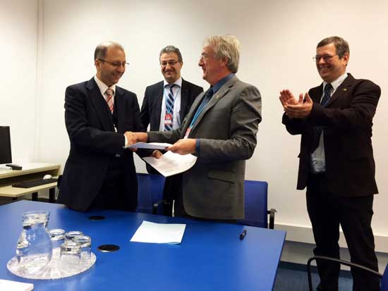
Mohamed Derdour, COMENA, Commissaire à l'énergie atomique
Hamid Aït Abderrahim, SCK•CEN Deputy Director-General
Eric van Walle, SCK•CEN Director-General
Vincent Massaut, SCK•CEN Business Development & Support Director
http://www.euronuclear.org/e-news/e-news-49/sck-cen-at-IAEA.htm

The BR2 research reactor of the Belgian Nuclear Research Centre (SCK•CEN) was in the limelight at the Annual General Conference of the International Atomic Energy Agency (IAEA), which was in Vienna from 14 to 18 September.
Belgium’s Minister of Energy, Marie Christine Marghem, visited the Belgian stand on the opening day. One of the eye-catchers is a scale model of the core of BR2, a matrix with beryllium channels. The BR2 reactor is currently undergoing a refurbishment programme which includes the replacement of this matrix. This operation ensures that BR2 will be operational for at least another 10 years after its scheduled restart in mid-2016 and assume its vital role in the production of medical radioisotopes. Until now, BR2 satisfied 25% of the global demand for molybdenum-99, the most commonly used medical radioactive isotope, and as much as 65% in peak periods. After its upgrade, the BR2 research reactor will be capable of producing 100% of global demand.
Later in the day, the operation was explained in detail at a special event surrounding the modernization of BR2, in the presence of Minister Marie Christine Marghem, Mr Willem Van de Voorde, Belgian Ambassador to Austria, Mr Juan Carlos Lentijo, Director of the Nuclear Fuel Cycle and Waste Technology Division of the IAEA and SCK•CEN director-general Eric van Walle. BR2 reactor manager, Steven Van Dyck, gave an overview of the reactor’s modernization operation and the outlook for isotope production and research. Minister Marghem talked about the pioneering role the Belgian Nuclear Research Centre has played for over 60 years now and was quite clear about the future.
“I am convinced that we will continue to be in the forefront of developments in innovative nuclear applications. Today, more than ever, Belgium is determined to keep the lead in this area.”
From left to right:
Willem Van de Voorde, Belgian ambassador in Austria
Marie Christine Marghem, Belgian Minister of Energy
Hamid Aït Abderrahim, SCK•CEN Deputy Director General
http://www.euronuclear.org/e-news/e-news-49/sck-cen-academy.htm


The Belgian Nuclear Research Centre (SCK•CEN) has concluded a Practical Arrangement with the International Atomic Energy Agency (IAEA) for cooperation in education and training of students and nuclear professionals.
Preserving and extending nuclear knowledge, skills and competences at the service of society is a key function of the SCK•CEN Academy for Nuclear Science and Technology. Extensive experience in nuclear science and technology, performing innovative research and the availability of large and unique nuclear facilities make the Belgian Nuclear Research Centre an important partner for education and training, both in Belgium and at an international level.
The arrangement between SCK•CEN and IAEA constitutes a structural framework for future activities with emphasis on:
Participation of SCK•CEN in IAEA research projects.
Participation in expert missions to assess applications from countries requesting support from the IAEA, and missions of the agency in the area of nuclear knowledge management, education and training.
Exchange and dissemination of knowledge and information relevant to countries that have recently initiated nuclear energy programmes or will do so in the future.
This agreement between SCK•CEN and the IAEA sets the framework for the next three years. The SCK•CEN Academy for Nuclear Science and Technology led by Dr Michèle Coeck is in charge of coordinating and implementing the various activities. Dr Coeck: “We have been working together constructively in the area of education and training for some time now and even more intensively since the SCK•CEN Academy was set up in 2012. The agreement is an official acknowledgement of our expertise. We will strengthen our ties with the IAEA and work together even more closely and extensively in the future."
The SCK•CEN Academy provides opportunities for Bachelor and Master students, PhD candidates and any professional interested in enriching his or her nuclear competences. Post-doc positions are also available. Teaching and research supervision are provided by members of the SCK•CEN research team. They share their knowledge ‘from the frontiers of nuclear science’ and oversee practical exercises that can be carried out using our centre’s nuclear facilities. Final-year pupils and teachers can also count on the SCK•CEN Academy.
http://www.euronuclear.org/e-news/e-news-49/ansaldo.htm

The MSSS facility at Sellafield was built just over 50 years ago as a facility for the underwater storage of Magnox swarf. This swarf was generated from Magnox fuel de-canning operations and a variety of other intermediate level solid wastes, termed miscellaneous beta-gamma waste (MBGW). Over the last 50 years, increased storage demands have seen the silo extended three times to give a total of 22 storage compartments. The operating floor of the building forms the roof of the compartments and spans all four parts of the building. Above the silos, a shop floor gave access to charge holes through which waste was deposited and is stored underwater.
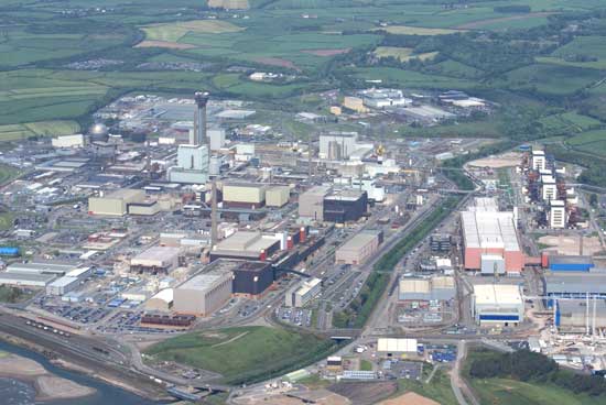
In June 2015, Ansaldo NES, fully owned by Ansaldo Nucleare and part of the Ansaldo Energia Group, achieved another important milestone for Sellafield Ltd, completing, at the Wolverhampton site, the testing and commissioning of the first of three Silo Emptying Plant (SEP) mobile caves. The SEP machine has been dismantled into almost 30 separate modules and transferred to the Ansaldo NES Beckermet facility, three miles from the Sellafield main gate entrance, waiting to be reassembled inside the Magnox Swarf Storage Silos (MSSS) building and tested before initiating solid waste retrievals in 2017.
.jpg)
The MSSS building at Sellafield is one of the site’s four Legacy Pond and Silo facilities and has been described as one of the most challenging industrial decommissioning projects in Europe. The Nuclear Decommissioning Authority (NDA) and Sellafield Ltd are focused on safely decommissioning these buildings as part of the hazard and risk reduction programme.
Since 1996, Ansaldo NES (then owned by Rolls-Royce) have been working with Sellafield Ltd on a project to design, manufacture, test and commission a bespoke solution to resolve this challenge. Three SEP machines are currently being constructed, tested and trialled by Ansaldo NES at Wolverhampton and are at varying phases of their lifecycle. Each of the fully assembled SEP Caves weights approximately 500 tonnes with dimensions of 11m x 5m x 6m and is assembled from over 13,500 parts each. These machines will be used to extract Intermediate Level Waste (ILW) from these compartments ready for transfer and processing.
The SEP machines will have to operate in a radioactive environment where operator access is restricted due to the radiation dose levels. Because of this, the machines will need to work safely and continually for up to 25 years without any modifications or upgrades. The SEP mobile caves are shielded cells that control a suite of waste retrieval tools and equipment. The tools are deployed, as required, to retrieve, re-size, reduce and consign to skips, the waste stored in each of the silos. The SEP machines are mounted on a substantial rail system, allowing them to be moved between silos as the retrievals operations progress. The exported skips will then be transferred to the future new facility, the Sellafield Direct Encapsulation Plant (SDP), for further processing and immobilisation of the waste.
Ansaldo NES is delivering to the MSSS programme with a dedicated Integrated Project Team, deployed across its headquarters in Wolverhampton as well as sites in Risley (Warrington) and Beckermet (Cumbria). Pro/Engineer 3D solid CAD modelling has been used extensively during the design process to allow design iterations with automatic updating of General Arrangement and Detailed Drawings. The final models are some of the most complex that have been produced using the ProE tool.
The ProE software has the advantage that it provides virtual prototypes which identify any design interface problems prior to manufacturing, thereby avoiding unnecessary re-work. Produced to support the 3D solid CAD modelling was a 1/10th scale model of the retrievals process. This model was used to validate and trial the effectiveness of various end effectors on the Second Stage Deployment arm and also to identify rope twist and wear issues.
The concept of the shielded cell can be simply described as a shielded box with tunnel and access penetrations to enable an operator to remotely control the retrievals operation without being exposed to radiation or contaminated material. The tools used to remove the waste itself have been designed and developed specifically for the retrievals process.
To meet the unique challenge of the retrieval operation, innovative bespoke tooling has been developed by Ansaldo NES and is evident in numerous areas of the SEP Mobile Caves.
.jpg)
A critical part of the design requirement was to ensure craters are not formed within the compartments being excavated. Additional structural constraints meant that the charge hole has a small aperture size through which all waste must be retrieved and the necessity to keep track of the positioning and rotational location.
In order to achieve the operational constraints, two important stages to the removals process were required. At the beginning of retrievals, a grab is used to retrieve waste near the charge hole and a solution was required to ensure that this would not result in the formation of craters. Ansaldo NES developed a ‘silo rake’ with the ability to form a flat bed of waste throughout the lifetime excavation of each silo compartment. Telescopic rake arms consisting of a series of rectangular sections that slide within each other on bearing pads were created using a serapid chain to extend and retract the arms. It also features a slewing mechanism, allowing the rake to rotate incrementally in relation to the top plate assembly.
After the waste is removed from the upper section of the silos, a more direct approach is employed which removes the need for the rake and increases the efficiency of the retrieval process. Engineers at Ansaldo NES developed the Second Stage Deployment (SSD) unit, able to deploy a ‘rope hung grab’ to a multitude of predefined positions within the silo compartment. A system, using two deployment arms to rotate and extend from 1.2m to 3.3m in a controlled manner within a tightly controlled space-envelope, allows all areas of the compartment to be accessed. The arms are able to deploy a minimum mass of 410kg through their full range of travel whilst managing the hydraulic supply hoses and maintaining a constant tool height within ±50mm while in motion.
Able to deploy to four ‘rope hand-over’ positions with the use of bespoke end deflectors and having the ability to park in a position to allow unhindered waste retrieval operations.
Significant time and cost was saved during the design stages by the innovative use of a 1/10th scale 3D model, able to simulate the behaviour and operation prior to full manufacture. This enabled the design process to be accelerated and directly interfaced with finite element analysis (FEA), for stress, seismic and impact assessments. Ansaldo NES undertook comprehensive verification of the results using a variety of alternative calculation methods to achieve this correlation.
http://www.euronuclear.org/e-news/e-news-49/saphymo.htm

In January 2015, the Stock Company "Production Association Electrochemical Plant", located in Zelenogorsk, Russia (formerly known as Krasnoyarsk-45), was declared the winner of the 2013-2014 TVEL challenge cup for "Best Fuel Company Enterprise for Civil Protection" at a nuclear facility. The competition is held every two years by TVEL, one of the world's largest producers of enriched uranium and isotope products.
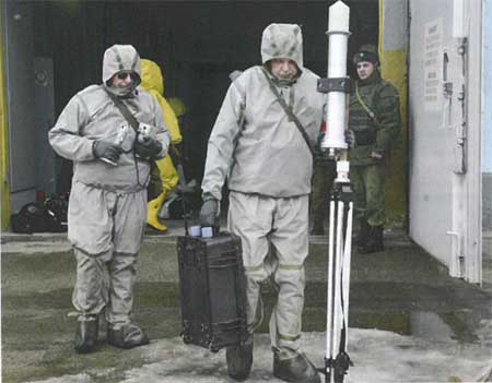
http://www.euronuclear.org/e-news/e-news-49/irsn.htm

IRSN has recently published the book "Nuclear reactor core melt accidents. State of knowledge" in its Science and Technical Series.
It provides with a very extensive and comprehensive overview of the whole topic of severe accidents, including the outcomes of the more-than-thirty-year activity carried-out by IRSN in the fields of phenomenology and simulation, and incorporates the lessons learned from major accidents which occurred in the world and the results of research and studies aimed at enhancing safety of existing and future power plants, as well.
It is intended to contribute to the dissemination of the existing knowledge in this major field of endeavor and to point-out the importance of safety research in a time of fading resources.
For more information visit: www.irsn.fr/LAGEN/
http://www.euronuclear.org/e-news/e-news-49/other-conferences.htm

![]()
17 -19 November
Bonn, Germany
more
![]()
17 - 22 April 2016
Charleston Mariott Hotel, Charleston, South Carolina, USA
more

10 - 12 May 2016
Hamburg, Germany
more

5 - 8 June 2016
Zadar, Croatia
more

July 2016
Pittsburg, USA
more

24 -30 July 2016
Hangzhou, China
more
5 -8 September 2016
Portorož, Slovenia
more

11 -16 September 2016
Boise, Idaho, USA
more
http://www.euronuclear.org/e-news/e-news-49/Member-Societies.htm

Austrian
Nuclear Society |
Belgian
Nuclear Society |
Bulgarian
Nuclear Society |
Croatian
Nuclear Society |
Czech Nuclear Society |
Finnish
Nuclear Society |
French
Nuclear Energy Society (SFEN) |
German
Nuclear Society (KTG) |
Hungarian
Nuclear Society |
The
Israel Nuclear Society |
Italian
Nuclear Association |
Lithuanian
Nuclear Energy Association |
Netherlands Nuclear Society |
The Nuclear Institute |
Nuclear
Society of Russia |
Nuclear
Society of Serbia |
Nuclear
Society of Slovenia |
Polish
Nuclear Society |
Romanian
Nuclear Energy Association (AREN) |
Slovak
Nuclear Society |
Spanish
Nuclear Society |
Swedish
Nuclear Society |
Swiss
Nuclear Society |
http://www.euronuclear.org/e-news/e-news-49/Corporate-Members.htm
Links to ENS Corporate Members |
Aachen Institute for Nuclear Training GmbH |
Alpiq Suisse Ltd. |
Andritz AG |
Ansaldo Nucleare S.p.A |
AREVA NP GmbH |
Atomexpo LLC |
Atomtex SPE |
BKW FMB Energie AG |
Chilean Nuclear Energy Commisssion |
Electrabel GDF Suez |
NV Elektriciteits-Produktiemaatschappij
Zuid-Nederland EPZ |
E.O.N Kernkraft GmbH |
Electricité de France (EDF), Communication Division |
Elektroinstitut Milan Vidmar |
ENUSA Industrias Avanzadas SA |
EXCEL Services Corporation |
GE Hitachi Nuclear Energy International |
IEA of Japan Co. Ltd |
Kernkraftwerk Gösgen-Däniken
AG |
Kernkraftwerk Leibstadt AG (KKL), |
L-3 Communications MAPPS Inc. |
Linn High Therm GmbH |
MVM Paks Nuclear Power Plant Ltd |
NRG |
NUKEM Technologies GmbH |
Paul Scherrer Institute |
SKB (Swedish Nuclear Fuel and Waste Management
Company) |
|
Studiecentrum voor Kernenergie, Centre d’Etude
de l’Energie Nucléaire SCK-CEN |
SVS FEM |
Synatom |
Teollisuuden Voima Oyj / Industrial Power
Company Ltd (TVO) |
Tractebel Engineering S. A. |
UNESA |
UniTech Services B.V. |
Urenco Limited |
Vattenfall AB |
VNS – Vinçotte Nuclear Safety |
VTT Nuclear |
Westinghouse Electric Company |
World Association of Nuclear Operators
(WANO), |
|
http://www.euronuclear.org/e-news/e-news-49/editorial.htm

Editorial Staff:
Lubomit Mitev, Editor-in-Chief
Contributors to this Issue:
Göran Blomberg (Studsvik Nuclear AB, Sweden)
Noel Carmarcat (ENS)
M.N. Cinbiz (Pennsylvania State University, USA)
Michèle Coeck (SCK-CEN, Belgium)
Kirsten Epskamp (ENS)
Kirsty Gogan (Energy for Humanity)
Lars Holt (YGN Germany)
Kristina Karlsson (Forsmarks Kraftgrupp AB, Sweden)
D.A. Koss (Pennsylvania State University, USA)
Andreas Moeckel (AREVA GmbH, Germany)
A.T. Motta (Pennsylvania State University, USA)
Terézia Melicherová (WiN, Slovakia)
David Schrire (Vattenfall, Sweden)
Realisation:
Marion Brünglinghaus
Avenue des Arts 56, BE-1000 Brussels
Phone +32 2 505 30 50 - Fax: +32 2 502 39 02
E-mail: info@euronuclear.org - http://www.euronuclear.org
The ENS News is a quarterly publication, in electronic
form only.
Copyright notice ©2015 European Nuclear Society.
Reproduction is authorised provided that the ENS News is acknowledged as the
source – except where otherwise stated.
![]()
© European Nuclear Society, 2015